Why Does Fertilizer Keep Flowing After the Dosing Pump Stops?
A pump can stop electrically while liquid keeps moving hydraulically. This guide separates a short discharge tail from continuing tank depletion, shows how to test the shutdown state safely, and turns the fix into a specified valve function rather than the word anti-siphon.
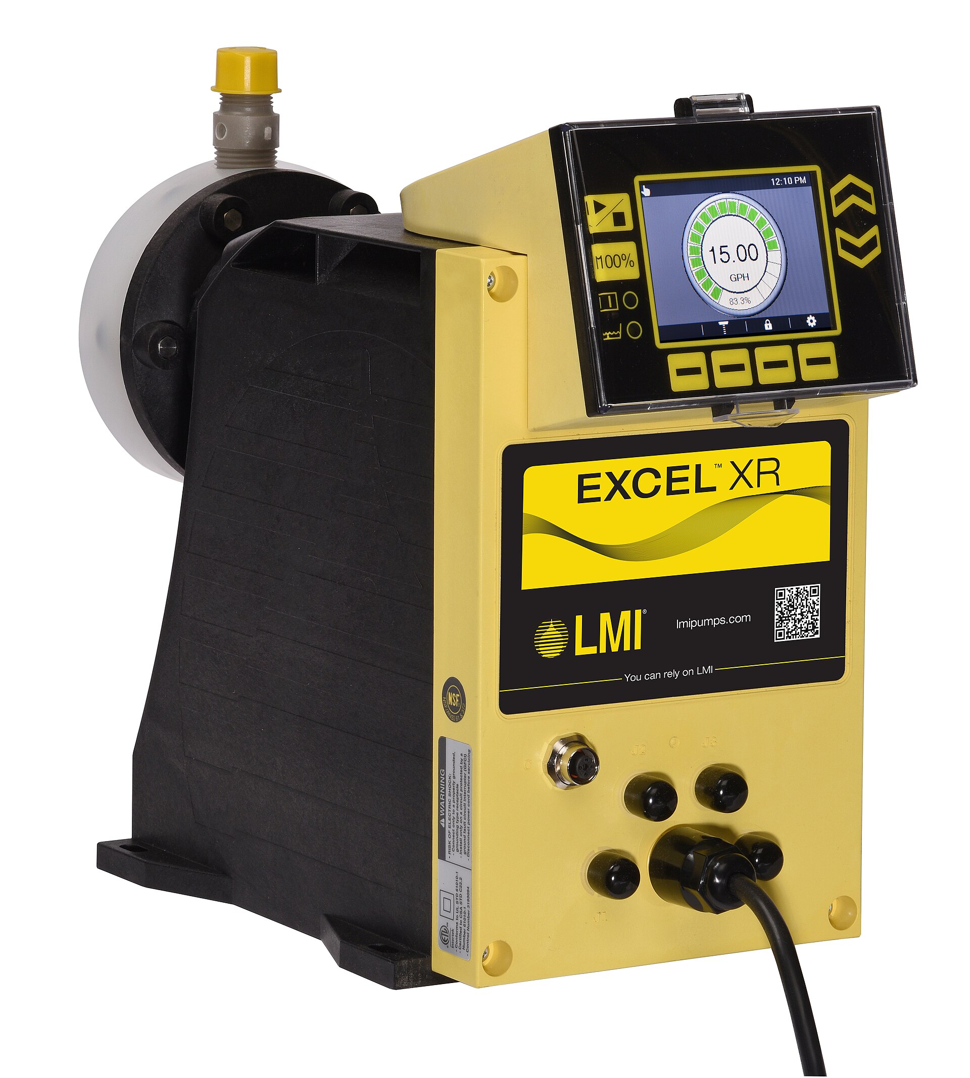
Disclosure: We may earn a commission if you purchase through links on this page, at no additional cost to you.
A fertilizer pump can stop electrically while the liquid keeps moving hydraulically. If the stock solution surface is above the injection point, an open liquid path may allow gravity to continue feeding the irrigation line. Pump manufacturers describe this pump-off flow as siphoning and identify suitable back-pressure or anti-siphon accessories as remedies. The important word is suitable: a generic check valve is not proof of protection against forward flow.
Before ordering a valve, establish which liquid is moving, in which direction, and for how long. A declining stock level, a few drops at a disconnected outlet, and water entering the stock tank are different observations. They require different corrections. This article concerns electric metering pumps feeding fertilizer stock into irrigation, rather than emitter drainage or the selection of a source-water backflow assembly.
Establish whether the pump really stopped
Start with the physical pump, not the irrigation controller screen. Check its operating indication and the actual drive or stroke activity using the manufacturer's procedure. Local manual mode, a maintained external signal, or another control input may explain continued operation. Record whether the irrigation pump stopped at the same time or remained running. Do not diagnose a hydraulic siphon while the metering mechanism is still delivering.
Next, verify direction. Continued stock loss toward the injection point suggests forward feed. A rising or diluted stock tank suggests reverse entry from the irrigation system. A wet floor or containment tray suggests leakage outside the intended path. Mark these as separate faults on the service record; an accessory installed downstream cannot necessarily control a leak upstream.
Use an isolated test arrangement and compatible test liquid approved for the equipment. Do not disconnect a pressurised chemical tube to see whether it drips. Where observation at the installed injection point is impossible, agree on a measurement method with the pump supplier before changing the pipework. A commissioning test should reproduce the relevant hydraulic conditions without releasing fertilizer or acid.
A short tail of liquid is different from continuing tank depletion
Record cumulative movement against elapsed time after the stop command. A discharge line can contain liquid and stored pressure; movement that decays and reaches a stable endpoint is different from a sustained supply drawn from the tank. Observation alone does not identify the precise internal cause, but it prevents replacing a pump solely because an outlet remained wet briefly.
Use a graduated vessel, calibration column, or another approved measurement arrangement with adequate resolution. Note the smallest change the instrument can resolve. "No visible movement" on a large stock tank is weak evidence when the potentially important volume is small. Likewise, a droplet count without droplet volume does not establish the quantity delivered.
Repeat the observation over successive equal intervals and record the stock level as well as any collected discharge. Continuous stock withdrawal after drive activity has ceased warrants investigation of the forward hydraulic path. A finite discharge without further stock withdrawal points toward a different boundary. Do not assign a universal allowable number of drops or minutes; derive acceptance from the process tolerance and equipment instructions.
Draw the highest tank level and the lowest discharge condition
Sketch the stock tank, pump, chemical tubing, valves and injection point. Use the highest normal liquid surface, including the level immediately after refill. Measure its vertical relationship to the injection point. Pump mounting height alone does not describe the available head: the source liquid surface and final discharge conditions matter.
Then list the receiving line states: normal irrigation pressure, a zone change, irrigation shutdown and any verified negative-pressure condition. A system that behaves correctly against a running mainline may behave differently when that pressure disappears. Test the state that permits unwanted flow, rather than demonstrating only the easiest operating condition.
For scale, consider an illustrative stock density of 1,200 kg/m³ and a liquid surface 2 m above the discharge elevation. The hydrostatic contribution is ρgh = 1,200 × 9.81 × 2, or approximately 23,544 Pa, equal to 0.235 bar. These are assumed inputs, not measurements from a particular installation. Recalculate with the actual solution density and elevations.
That calculation is a diagnostic input, not a valve setting. It does not include every pressure effect in the system, and different valves reference pressure differently. Ask the manufacturer how upstream pressure, downstream pressure and its stated adjustment affect opening and reseating. A catalogue value cannot be applied correctly until those definitions are known.
Buy the required function rather than the word check
Forward feed and reverse flow are separate duties. A nonreturn valve may stop irrigation water returning toward the tank while still opening in the normal dosing direction under gravity. The question is whether the exact assembly provides the required anti-siphon resistance under the installed conditions. Some injection valves combine these functions; manufacturers describe such combined accessories explicitly. That does not establish equivalent behaviour for every injection check.
| Component or function | Purpose in this fault | What still needs confirmation |
|---|---|---|
| Anti-siphon or back-pressure device | Resists unwanted forward feed under specified conditions | Opening and reseating behaviour at actual inlet and outlet pressures |
| Injection nonreturn valve | Restricts reverse entry from the irrigation line | Whether the exact model also has an anti-siphon function |
| Pressure relief arrangement | Provides a route for excessive discharge pressure | Set pressure, capacity and safe return destination |
| Positive isolation device | Provides the specified closed-state isolation | Leakage criterion, compatibility and behaviour on loss of power |
Relief and back-pressure functions should not be confused because a similar valve body appears in both arrangements. Manufacturers distinguish excessive-pressure protection from siphon prevention. An inline restriction and a bypass return are different hydraulic arrangements; use the exact installation drawing for the selected device.
If the process requires no chemical entry during shutdown, specify that requirement explicitly. Do not assume "anti-siphon" means a certified zero-leak shutoff. Obtain a closed-state leakage criterion and the manufacturer's proposed isolation arrangement. A relief valve also cannot make an undersized pump overcome a higher injection pressure; its purpose is pressure limitation, not pressure multiplication.
Keep the pump inside its pressure capability
The running pump must deliver the required stock flow against the actual system resistance. Collect the pump's pressure-dependent capacity data, the receiving line's operating range, tubing and fitting ratings, and the proposed valve's performance information. Check the complete duty at the highest expected receiving pressure as well as the pump-off condition at the lowest pressure.
Do not simply add a guessed valve setting to a normal mainline gauge reading and call the result a design. Ask whether the selected back-pressure device controls an upstream pressure or maintains a differential, and how downstream pressure affects it. This distinction determines which pressure comparison is valid. Require the supplier to identify the model and reference the applicable drawing or curve.
Increasing resistance can change delivered volume, so verify actual dosing after the final hydraulic arrangement is installed. The acceptance quantity is the stock volume delivered under the intended operating conditions, not the controller's nominal percentage. If pressure capability is inadequate, resolve the pump and system selection rather than suppressing the symptom with an arbitrary adjustment.
For a peristaltic pump, follow the exact pump manufacturer's installation guidance. Do not assume that roller occlusion remains a dependable isolation function under every tube condition, or that an added valve is within the pump's pressure capability. A public water-treatment discussion describes a suction-side tube rupture below an elevated tank. It is a useful reminder to locate the failure before choosing a discharge accessory, rather than evidence that a particular valve would solve that rupture.
Also check where pressure can become trapped during isolation. Adding a closing valve changes the operating arrangement if the metering pump can continue stroking against it. Have the equipment supplier confirm the pressure-protection provision and the control sequence together. A drawing that shows only normal flow leaves this transition unresolved. The bypass or relief return must lead to an appropriate destination; it should not create an unreviewed connection between incompatible stock solutions.
Turn the shutdown test into an acceptance record
A useful test sheet names the pump and valve models, stock or test-fluid identity, density where relevant, tank level, measured elevations, tubing size, receiving pressure, valve adjustment and measurement resolution. Record the stop time and subsequent volume readings. Without those conditions, a supplier cannot tell whether two apparently conflicting tests were actually comparable.
Include a full-tank condition because a test near empty may miss the larger available head after refill. Include the lowest receiving pressure expected in operation. Where the design depends on powered isolation, verify the documented loss-of-power response. Where an irrigation-flow interlock is fitted, verify its actual response rather than accepting the wiring diagram alone.
Agree on two separate acceptance statements: normal dosing meets the specified delivery tolerance, and pump-off transfer stays within the defined process limit over the agreed observation period. State the instrument resolution alongside the result. Passing one statement does not establish the other. Keep a dated baseline so future valve service or tubing replacement can be checked against the same conditions.
Consider an illustrative acceptance record with three observations: the drive stops, a measured quantity leaves the discharge tube, and the stock measurement then remains stable. That record supports a finite post-stop event within the measurement limits. If stock withdrawal instead continues during each subsequent interval, the record supports a continuing feed path. Neither observation alone proves which internal valve surface is responsible. Retain the measurements and investigate the assembly rather than naming a failed part prematurely.
If the result changes after maintenance, examine what changed before adjusting anything: assembly orientation, diaphragm or seal identification, deposits, tube routing, tank level and receiving pressure. Use the service instructions for cleaning and replacement. An undocumented spring adjustment may conceal a fault and leave the next technician without a reproducible starting point.
A small tube valve to investigate with the supplier
For buyers standardising compact dosing assemblies, the Alibaba listing below is a relevant inquiry lead. The seller lists a small-tube back-pressure valve described as model BK606/08 and states that it can prevent gravity feed under static conditions, with PP or PVDF body options, a PTFE diaphragm, 6 mm or 8 mm tube connections, a one-year warranty and a five-piece minimum order. This is seller information, not independent performance validation or an installation recommendation.
The delivered material variant and whether the tube dimension means inside or outside diameter remain unconfirmed. Its stated "0–8 bar" pressure field does not establish whether this is an adjustment range, a pressure rating or another limit. Do not design around that field without a model-specific datasheet. Ask for the actual manufacturer, exact part number, connection drawing, pressure-flow information, wetted-material schedule and written compatibility for the intended fertilizer concentration and temperature.
Keep the sample specification attached to the eventual repeat order. Record the supplied body option, seal and diaphragm materials, tubing dimensions, adjustment instructions and any approved substitutions. A repeat purchase under the same marketplace title may still require checking the actual part supplied. If the seller cannot identify the manufacturer or explain the pressure field, retain the offer as an inquiry lead and seek a documented alternative before installation.
Give the supplier a fault description they can answer
Send the measured maximum stock level, injection elevation, minimum and maximum receiving pressures, required dosing flow and pump pressure capability with the inquiry. Describe the unwanted transfer as a volume over time after a verified stop. Ask the supplier to mark valve orientation, pressure references, relief routing and any necessary isolation on one drawing. Require the proposal to explain both running delivery and shutdown behaviour.
Purchase against that documented duty and an agreed sample test, rather than the broad label "anti-siphon valve". The practical objective is measurable: the pump delivers the intended fertilizer while commanded to run, and the installed assembly limits unwanted transfer when it stops. Preserve the test conditions with the purchase record so the same component can be reordered and checked consistently.
Share this article