Where Should an EC Sensor Go in a Fertigation System?
An EC probe measures the liquid around its electrodes, not the recipe on the controller screen. This guide maps the four measurement points, explains why the control probe belongs after injection and mixing, and turns placement into an RFQ and commissioning test.
Disclosure: We may earn a commission if you purchase through links on this page, at no additional cost to you.
An EC probe does not measure "fertilizer" in the abstract. It measures the conductivity of the liquid that is actually around its electrodes at that moment. Put the probe beside a concentrated injection point, in a stagnant stock tank, or in a poorly mixed bypass and the controller can make a confident decision from an unrepresentative sample. The result may be an unnecessary dose correction, an alarm that operators learn to ignore, or a crop receiving a different solution from the one shown on the screen.
The practical question is therefore not simply whether a fertigation system needs an EC sensor. It is which measurement point answers the buyer's decision: source-water correction, stock preparation, delivered-feed control, or drainage diagnosis. This guide maps those points, explains why the primary control probe normally belongs downstream of the injection and mixing section, and turns the decision into an RFQ and commissioning test. It does not replace a crop recipe, a nutrient analysis or a local agronomist's interpretation of salinity.
Start with the decision the reading must support
| Measurement point | Question it can answer | What it cannot prove |
|---|---|---|
| Source or make-up water | What background EC enters the system, and how much of the target signal is created by fertilizer rather than the water supply? | It cannot prove that the final nutrient recipe is correct; the same EC can come from different ions. |
| Stock tank | Is the prepared stock dissolved and within the sensor's range before injection? Is a batch drifting or settling? | It does not show the concentration delivered after the injector ratio, dilution and line mixing are applied. |
| Post-injection feed line | What EC is actually travelling toward the irrigation manifold or crop zone after the stock has mixed with irrigation water? | It cannot identify which individual nutrient is high or low, and it is not automatically a substitute for injector-ratio calibration. |
| Drain or return stream | Is the root zone or recirculating loop accumulating or losing salts relative to the feed? | It cannot be used as the sole set point for a fresh-feed recipe when uptake and water balance change the ion mix. |
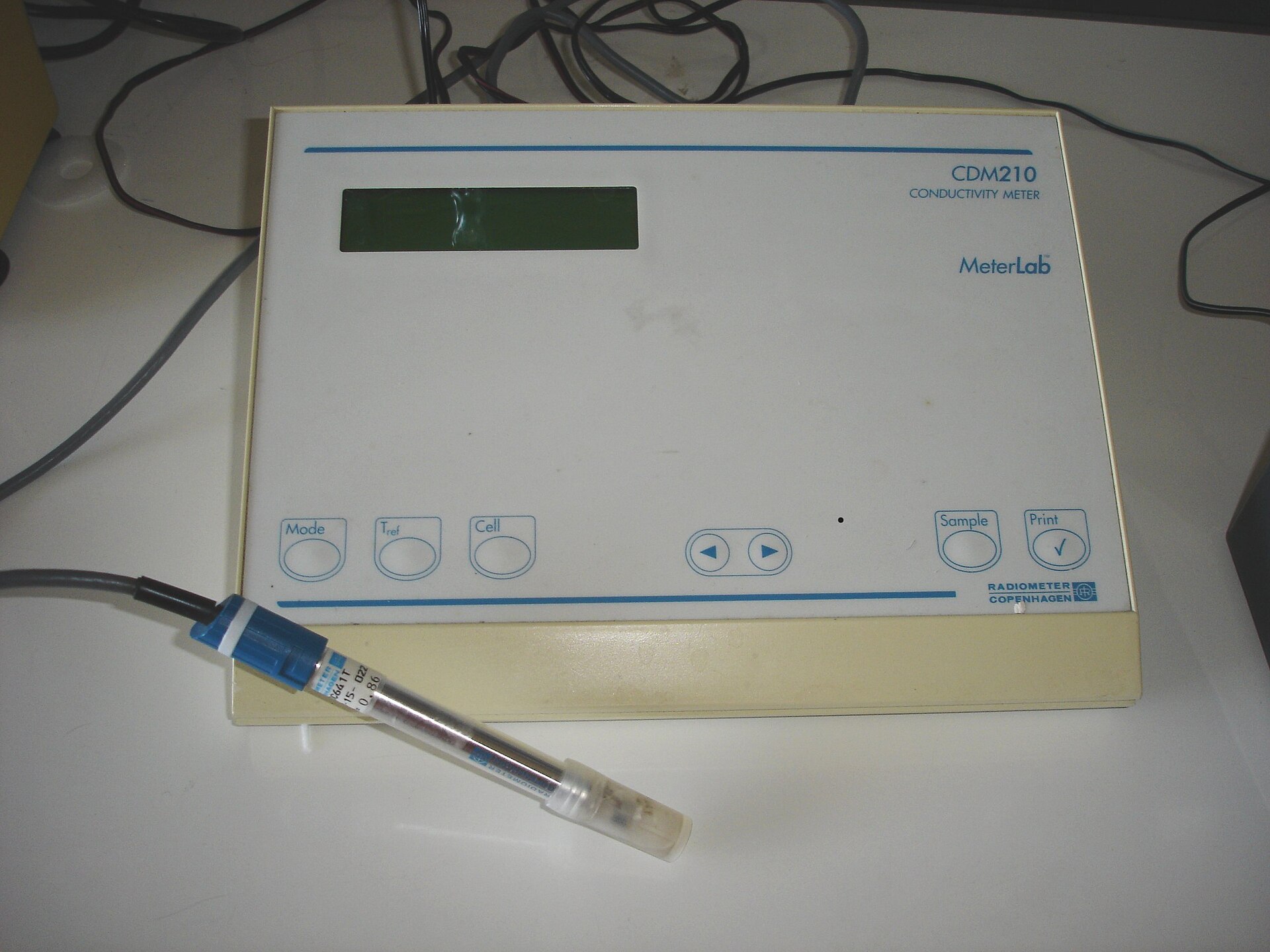
Many installations need two different instruments rather than one probe doing every job: a fixed sensor for the control point and a calibrated portable meter for independent grab-sample checks. This is especially important when the fixed sensor is connected to a dosing loop. A second display fed by the same probe is not an independent verification.
Where the primary control probe normally belongs
For a proportional or pump-driven system, the primary probe normally belongs in a representative stream after fertilizer has entered the irrigation water and the available mixing length or static mixer has done its work. Extension guidance treats EC monitoring as a way to avoid exceeding a crop's salinity limit, while fertigation-control studies place the measurement in the mixed discharge line. The probe should see the liquid sent to the crop, not a concentrated plume beside the injection tee.
"After mixing" is hydraulic, not a fixed distance. Pipe diameter, flow, injection method, pump pulsation, bends, mixers and valve changes all matter. Too close to a diaphragm or peristaltic pump, the probe may see alternating slugs; in a dead leg it may see an old sample. Specify flow direction, injection point, mixer or straight-run, sample take-off and the transport time for a step change.
Placement detail
| Placement detail | Acceptance question |
|---|---|
| Hydraulic position | Is the probe downstream of all fertilizer injection points and any mixing element that the design relies on? |
| Representativeness | Does liquid at the probe have the same formulation and temperature as the water entering the irrigation manifold? |
| Flow condition | Is there a stable, bubble-free flow at the sensor's specified range, without a pump suction vortex or intermittent empty pipe? |
| Service access | Can an operator remove, rinse, calibrate and replace the probe without draining the whole fertigation skid? |
| Control delay | Has the controller's alarm or dosing response accounted for transport time between injection and measurement? |
A probe immediately after the injector can still be useful for commissioning if the line is designed to mix there, but the supplier must show the mixing basis. Do not accept "inline" as proof of a valid measurement point. The word describes the hardware form, not the quality of the sample.
When a stock-tank or flow-cell installation is better
An immersion probe in the stock tank can answer a batch-preparation question, particularly when the tank is mixed or recirculated and the operator needs to confirm that a formulation has dissolved before release. It is a poor control point when the tank is stratified, the probe sits near a dosing inlet, or the stock concentration is outside the probe's specified range. The probe should be kept away from a concentrated chemical jet and from the tank wall or bottom; the supplier's mounting drawing should state the immersion depth and clearance.
A flow cell gives a repeatable sample when the main line is too large, pressurised or difficult to service. Separate inline, flow-cell and reservoir-immersion arrangements exist, with pressure limits and a controlled flow-cell valve. A flow cell still needs a clean sample path, known flow, isolation valves, a drain or return route, and protection against bubbles or stagnant liquid. Request the probe, transmitter, flow cell, fittings, pressure rating and cleaning procedure as one assembly.
| Use case | Preferred arrangement | Do not approve until |
|---|---|---|
| Automatic correction of delivered fertigation | Inline probe or controlled flow cell after injection and mixing | The supplier documents range, temperature compensation, pressure, output protocol and step-response or transport treatment. |
| Batch release from an A/B or single stock tank | Immersion probe in a demonstrably mixed tank, or a recirculation flow cell | The mixing method, sample location, concentration range and cleaning or verification routine are defined. |
| Small greenhouse or service check | Portable EC meter used on a representative sample | The meter is calibrated with an in-date standard and the sample is not taken from a surface layer, foam or concentrated plume. |
| Closed-loop or recycling system | Feed and selected drain or return measurement points | The team understands that an EC trend does not identify individual nutrient depletion and is paired with recipe and water-balance checks. |
Calibration is part of placement
A correctly located probe can still produce a bad control decision if the calibration record is weak. Purdue Extension recommends a known standard, a target-value check and fresh standard, rather than returning used solution to the bottle. UMass Extension likewise requires an EC standard for consistent readings. Record the standard, temperature, date, probe serial number, transmitter setting and separate sample comparison.
Use clear-water subtraction carefully. UNH Extension measures unfertilized irrigation water, measures after injection, and subtracts the first value before comparing with the fertilizer label or product table. This checks the selected sampling point; it does not turn EC into a universal nitrogen meter. Fertilizer blend, source-water ions, temperature compensation and range all change the EC-to-ppm relationship.
| Commissioning step | Record |
|---|---|
| 1. Verify the sample path | Injection location, mixing element or length, probe location, pipe size, flow direction, pressure and isolation valves. |
| 2. Calibrate the probe | Standard value, temperature, expiration date, calibration method, probe ID and transmitter output. |
| 3. Compare with a reference | A separate calibrated meter, sample time, sample location, temperature and difference from the fixed reading. |
| 4. Run a controlled step | Start or change the injector, log the time at injection and at the sensor, and check for spikes, delay or oscillation. |
| 5. Set the response | Alarm band, low/high action, sensor-fault action, manual fallback and the person responsible for reviewing trends. |
If the fixed probe and portable meter disagree, do not immediately change the dose. Take a fresh mixed sample, check temperature compensation, rinse the probes, verify the standard and inspect the sample line for bubbles or a blocked filter. A bad automatic correction can harm a crop as easily as an underperforming injector.
Two sourcing roles for this decision
The two roles below are different instruments, not competing versions of the same purchase. One is a fixed sensor intended for a documented control point; the other is a portable check that protects the operation from trusting a single probe. Marketplace fields are seller or platform statements and must be confirmed for the exact delivered variant.
RFQ wording for an EC measurement point
Please quote an EC measurement assembly for [source/feed/drain] water in a fertigation system. The measurement point is [location] downstream of [injection point or mixer], with pipe size [size], operating flow [range], pressure [range], temperature [range], expected EC [range] and fertilizer formulation [name/concentration]. State the sensor principle and cell constant; measurement range and accuracy at the stated temperature; automatic-temperature-compensation method; wetted materials and gasket materials; pressure and flow limits; response time; output (RS485/Modbus, 4–20 mA or other); power; cable length; calibration standard and procedure; flow-cell or insertion dimensions; cleaning and replacement parts; manual revision; MOQ; lead time; warranty; and a sample installation drawing. Confirm whether the quoted range and accuracy apply to the exact probe and transmitter supplied, not only to a product family.
Acceptance checks before automatic dosing
| Check | Pass condition |
|---|---|
| Location | The probe reads a representative, mixed stream and is not beside an injection plume, dead leg, air pocket or unflushed branch. |
| Range | The expected clean-water, mixed-feed and upset values are inside the exact delivered probe's specified range. |
| Calibration | The probe is calibrated with an in-date standard and the recorded result is within the agreed tolerance. |
| Reference check | A separate calibrated meter agrees with a fresh sample at the same time and temperature, within the project tolerance. |
| Control response | A known injection change produces a plausible, time-aligned response without uncontrolled oscillation. |
| Failure mode | A disconnected, fouled, out-of-range or implausible signal triggers a defined alarm or safe fallback rather than an unreviewed dose change. |
Bottom line
Put the primary EC sensor in the mixed stream that represents what the crop receives, usually downstream of injection and adequate mixing. Use the stock tank for batch-release checks and the drain or return line for a separate nutrient-balance question. Calibrate with a known standard, verify independently, and never treat EC as a one-nutrient measurement. A product page is only a lead until range, cell constant, pressure, materials, drawing, calibration and controller response are documented.
Share this article