How to Wire a 4–20 mA or RS485 pH Sensor to a Fertigation Controller
A pH value on the screen is not proof that the loop is correct. This guide treats electrode, transmitter, controller scaling, relay outputs and dosing interlocks as one signal path, and gives a bench-to-production test sequence.
Disclosure: We may earn a commission if you purchase through links on this page, at no additional cost to you.
The practical answer: wire the sensor, controller input, power supply, communication settings and dosing interlock as one measurement loop. A pH value appearing on a screen is not proof that the loop is correct. The controller may be scaling 4–20 mA against the wrong range, reading the wrong Modbus register, powering a transmitter incorrectly, or leaving a chemical pump enabled when the signal fails.
This guide is for greenhouse, hydroponic, nursery and irrigation teams integrating an online pH point into a fertigation controller, PLC or remote logger. It is deliberately narrower than a general pH-probe buying guide: the decision is how to specify and commission the signal path so the displayed value, logged value and dosing action mean the same thing. Terminal numbers and wire colours are model-specific; the current manual for the exact shipped variant always overrides a generic diagram.
Start with the signal architecture, not the product title
Online pH products sold into agriculture often combine several functions in one listing: a glass electrode, a temperature input, a transmitter, a display, relay contacts, 4–20 mA outputs and RS485/Modbus. Treating that as one "pH sensor" creates avoidable purchasing errors. Draw the loop before requesting a quote.
| Layer | What it does | Typical question | Acceptance evidence |
|---|---|---|---|
| Electrode and temperature | Creates the electrochemical measurement | Is the electrode compatible with the sample and temperature input? | Calibration record and stable buffer response |
| Transmitter or input | Converts the measurement to a current or digital value | Is the input loop-powered, externally powered, or RS485? | Measured loop current or a valid Modbus frame |
| Controller scaling | Turns the signal into pH units | Does 4 mA equal the documented low range and 20 mA the high range? | Two-point simulated-input test |
| Control output | Permits or blocks acid/base dosing | What happens on sensor fault, timeout, or out-of-range value? | Alarm and pump-interlock test |
4–20 mA: the simplest loop that is easy to miswire
A 4–20 mA signal represents a measured range as current. The relationship is normally linear, but the endpoints belong to the configured instrument. If a transmitter is set for pH 0–14, 4 mA represents the low end and 20 mA the high end; if the controller is configured for pH 2–12, the same current produces a different displayed value. Never infer the scale from the product title.
First identify the electrical arrangement. A two-wire loop-powered transmitter receives its supply through the same pair that carries the signal. An externally powered transmitter may provide a separate supply and a signal pair. A three- or four-wire device may share a reference or provide isolated outputs. Connecting a powered output to a controller terminal intended to supply loop power can damage the input; connecting a passive loop to an input that expects an active voltage can produce a dead or saturated reading. The manual must state which arrangement applies.
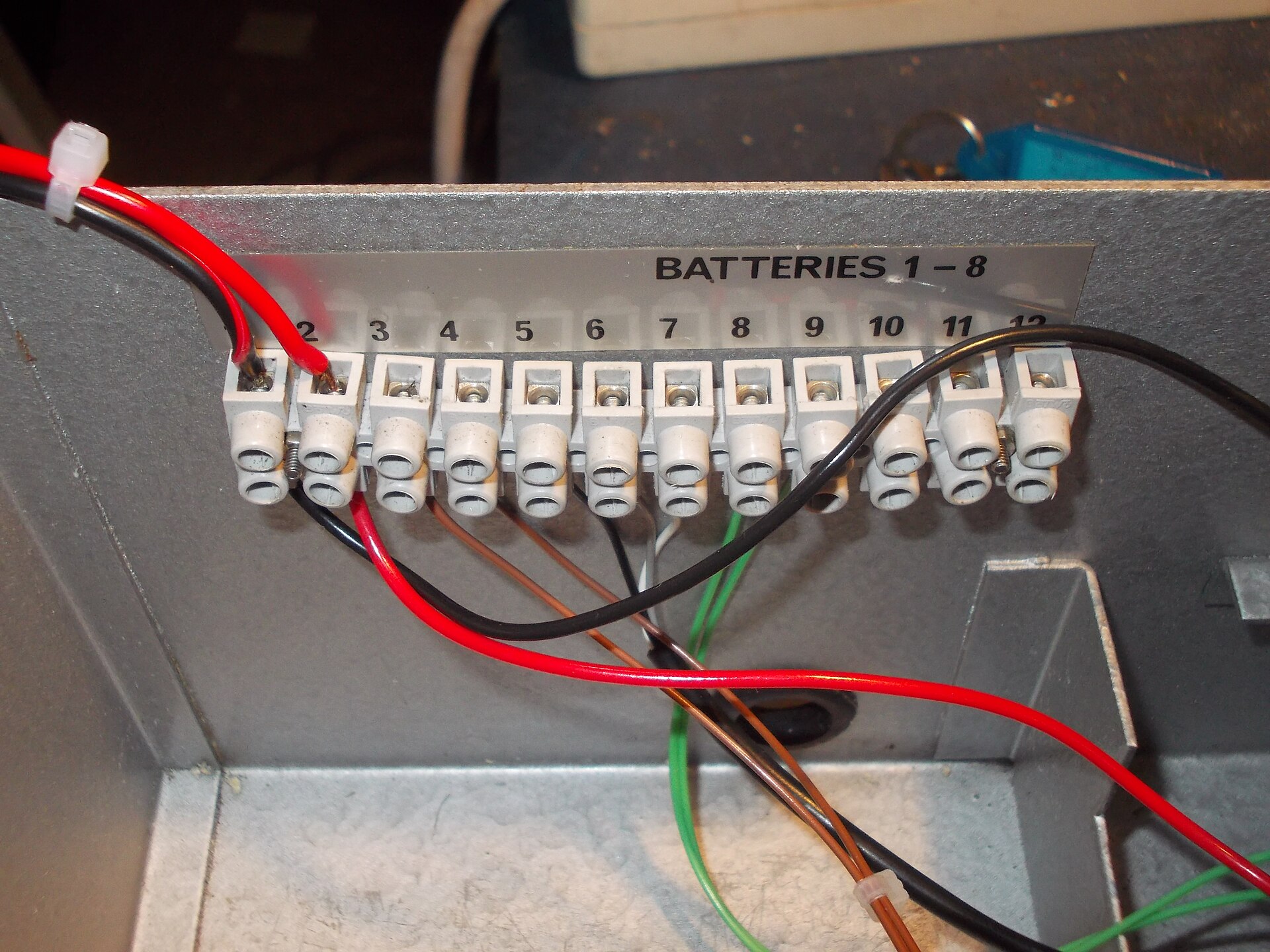
Use a wiring schedule with terminal name, wire function, polarity, supply voltage, shield termination and destination. Keep low-level pH or analogue wiring away from dosing-pump power and motor cables. If the manual specifies shielded cable, terminate the shield exactly as instructed, often at one end, to avoid creating a ground loop. Label both ends before energising. A photograph of the finished terminals is useful for service, but it does not replace a current measurement.
The commissioning test for an analogue input
- Power the transmitter with the specified voltage and verify the supply at the device terminals under load.
- Measure the loop with a suitable current meter or loop calibrator without breaking the circuit in an unsafe way.
- Confirm the controller input type, low and high range, engineering units, damping, alarm limits, and upscale or downscale fault action.
- Inject or simulate at least two known current points, such as the configured low and high endpoints, and record the displayed pH.
- Return to the real probe, calibrate with the approved buffers, compare the online reading with a verified handheld sample, and only then enable automatic dosing.
RS485/Modbus: digital does not mean plug-and-play
RS485 is the physical electrical layer; Modbus RTU is the communication protocol often placed on it. A working cable can still deliver wrong data if the slave address, baud rate, parity, stop bits, function code, register address, byte order or scale is wrong. Documented default addresses and serial formats belong to a specific model, not to every pH sensor.
A/B labels are not consistently interpreted between vendors. If the master times out with the correct settings, check the exact terminal legend and, where permitted, test the vendor's polarity convention rather than assuming A must connect to A. Provide a signal reference or common where the manual requires one. Termination and biasing are bus design questions; a short one-sensor bench test and a long multi-drop greenhouse run may need different treatment.
Read the register map as an engineering document
Before writing PLC or logger logic, capture the following fields in the integration sheet: slave ID; baud, parity and stop bits; function code; register type; zero-based or one-based address convention; number of registers; signed or unsigned data type; decimal scale; byte or word order; temperature-compensation flag; and the invalid-value or sensor-fault code. Ask the supplier for a sample request and response frame, including CRC, rather than accepting "Modbus supported" as sufficient evidence.
Bench-test one device at a time. Read the documented temperature and pH registers, change the probe condition in a controlled buffer, and verify that the raw value changes in the expected direction and scale. If a library returns a constant error code, do not reinterpret it as pH. Check address, CRC, register type, wiring polarity, common reference and serial settings first. Only after the raw frame is correct should the value be mapped into the fertigation controller.
Relays and dosing pumps: the safety boundary
Many online pH controllers advertise high and low relay outputs. A relay contact is a control interface, not automatically a complete pump starter. Confirm whether the contact is dry or powered, its voltage and current rating, the pump's inrush current, and whether an interposing relay, contactor, fuse or suppression device is required. Keep the pH instrument's low-voltage signal side separated from the mains or motor circuit.
Define the fault state before connecting a chemical pump. A disconnected probe, invalid Modbus value, lost 4–20 mA loop, failed temperature input or communication timeout should not silently become a normal pH value. The controller should alarm and move the dosing output to the documented safe state. Test this with the pump disabled first, then with a controlled dry run, and finally during water-only operation. A correct pH display with an unsafe fault response is not an acceptable installation.
The mistakes that look like sensor failure
A few field symptoms recur because the interface is being interpreted at the wrong layer. A value fixed at 0, 4 or 20 mA often points to an open loop, wrong power arrangement, saturated input or a configured fault current, not necessarily a dead electrode. A plausible but wrong pH value often points to endpoint scaling, a decimal multiplier or the wrong Modbus register. A noisy value that changes when a dosing pump starts can indicate cable routing, grounding or a shared power problem.
Treat each symptom as a testable hypothesis. Disconnect the real controller input only under a safe procedure; use a loop calibrator or a simulator where possible. For RS485, capture the raw request and response rather than relying on the HMI value. For a relay, verify the contact state with the load isolated. This approach prevents a technician from replacing a probe when the real fault is a one-line PLC scaling parameter.
Create an integration record that another technician can reproduce
The final handover should contain more than a wiring photograph. Include the exact product and controller model, firmware or document revision, terminal schedule, supply measurement, analogue scale or Modbus map, calibration buffers and results, handheld comparison, alarm settings, and the date of the first production check. Record the normal pH, temperature, current or raw register value, and controller display in the same row. If a later value changes, the team can identify whether the change came from chemistry, calibration, configuration or hardware.
For a multi-zone system, record which controller input belongs to which sensor and which dosing output. Duplicate Modbus slave IDs, copied register maps and swapped zone labels are common during expansion. Label the cable at the sensor, panel, junction box and terminal block. A small amount of documentation at installation is cheaper than a crop-cycle investigation after two zones have been dosed incorrectly.
A repeatable integration sequence
- Freeze the process. Put acid/base dosing in manual or maintenance mode and record the current pH, temperature, flow state and controller configuration.
- Match the documents. Obtain the exact sensor model, transmitter revision, terminal diagram, output option, register map and controller input manual. Do not wire from a similar-looking listing photo.
- Wire power and signal separately. Check voltage, polarity, loop arrangement, shield, common reference and cable routing before connecting the electrode.
- Prove the signal. Use a loop test for 4–20 mA or a bench Modbus master for RS485. Record the raw current or frame and the controller's conversion.
- Calibrate the measurement. Condition and calibrate the probe with fresh buffers according to the electrode manual. Record slope and offset if the instrument exposes them.
- Compare locations. Compare the online value with a verified handheld sample from the same mixed stream. Note temperature and sampling position.
- Test faults and interlocks. Open the loop, stop the transmitter, create a communication timeout, or use the controller's simulation mode. Confirm alarm, data-quality flag and pump response.
- Release to production. Enable automatic dosing only after the acceptance record is signed and a first-run comparison is scheduled.
What to put in the RFQ
A useful request asks for a complete integration package, not only a range and accuracy number:
- Exact sensor and transmitter model, revision, electrode type, temperature-compensation method, connector, cable length and replacement part number.
- Electrical arrangement: supply voltage, loop-powered or externally powered 4–20 mA, isolated or non-isolated output, RS485 terminals, signal common and maximum cable length.
- For Modbus: default address, baud/parity/stop bits, supported function codes, register map, scale, data type, byte order, CRC example and fault codes.
- For relays: dry-contact or powered output, contact rating, hysteresis, delay, alarm logic, and recommended interposing hardware for the dosing pump.
- A wiring drawing for the exact variant, calibration procedure, sample commissioning record, warranty boundary and spare-electrode availability.
- A test plan covering low and high analogue points or known Modbus values, buffer calibration, sample comparison, signal loss, communication timeout and safe dosing shutdown.
If the controller is already installed, attach a photograph of its input card and the existing terminal schedule to the RFQ. Ask the supplier to mark the proposed connection on that drawing and to state any required isolator, converter, termination or pull-up hardware. This simple review catches incompatible "RS485" claims and active/passive 4–20 mA mismatches before a sample is shipped. It also gives the buyer a written answer when the supplier later changes the connector, firmware or output option.
Two sourcing roles for this integration task
The candidates below are role-based. Marketplace fields are seller or platform statements; exact output options, shipped variants, documents and field performance require RFQ confirmation.
Bottom line
The safest pH integration is not the one with the most outputs. It is the one whose electrical arrangement, scaling, register map, fault state and dosing interlock are documented and tested as a single loop. Buy the sensor and controller as compatible roles, request the exact wiring and Modbus documents, prove the signal on a bench, compare it with a calibrated sample, and test what happens when the signal disappears. That sequence turns a marketplace listing into an auditable control point.
Share this article