What to Check Before Buying a Pressure Relief Valve for a Fertilizer Dosing Pump
A blocked discharge turns a small dosing pump into a pressure problem. This guide sets the opening pressure from the whole pressure boundary, checks capacity at the real flow, and specifies where the bypass must return.
Disclosure: We may earn a commission if you purchase through links on this page, at no additional cost to you.
Select the valve only after its setting, full-flow capacity, wetted materials and bypass route are documented for the exact pump and fertilizer solution. A marketplace listing that shows a pressure rating and a diaphragm material does not supply enough information for technical approval.
A blocked discharge can turn a small dosing pump into a pressure problem
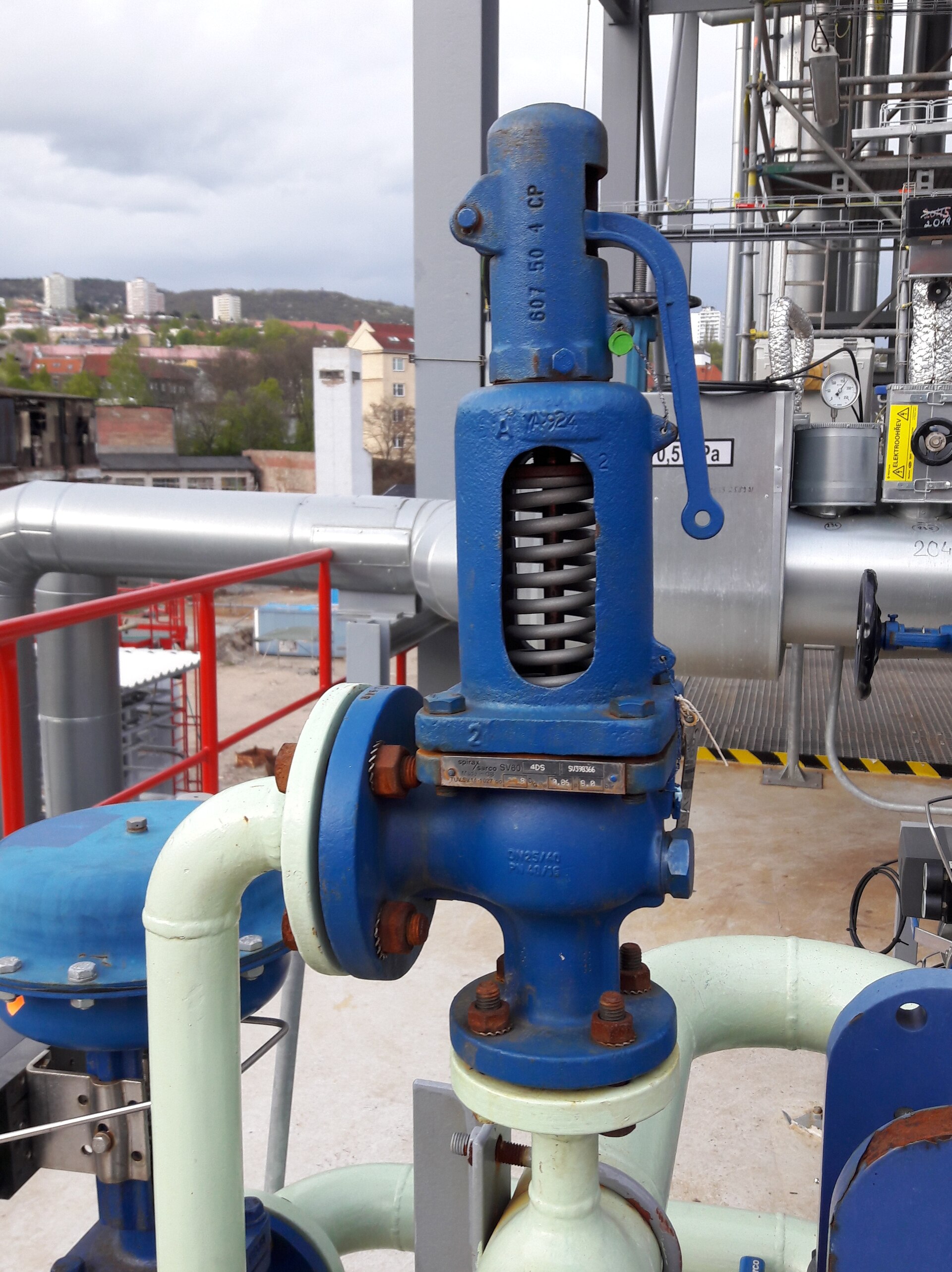
A positive displacement dosing pump keeps moving a defined volume on each stroke or revolution. If a downstream valve closes, an injector plugs, or a line freezes, the pump may continue to push liquid into a volume that cannot accept it. Pressure then rises until something yields: a hose, fitting, pump head, diaphragm, seal or the line itself. A pressure relief valve gives that flow another route before the weakest component is damaged.
For fertilizer injection, the useful buying question is not simply "what pressure is this valve rated for?" It is whether the valve can open at a defensible setting, pass the pump's full output under the actual conditions, and return the chemical to a safe point without creating a new hazard. The valve is an overpressure safeguard. It is not a substitute for a correctly sized pump, a pressure controller, or a properly designed injection point.
This guide concerns an external, spring-loaded relief or bypass valve installed on the discharge side of a positive displacement chemical metering pump. It does not size industrial safety valves under pressure-vessel codes, and it does not cover a pump's internal hydraulic relief. Follow the manual for the exact pump and valve model, plus the rules that apply to the installation.
First decide what the valve must do
A relief valve opens when upstream pressure reaches its setting and diverts flow to a lower-pressure destination. In a dosing installation, that destination is often the chemical tank or the pump suction, provided the pump and system manufacturer permit that arrangement. The normal process flow should still travel toward the injection point when the valve is closed.
Do not confuse this function with a back-pressure valve. A back-pressure valve creates a minimum downstream pressure to stabilise metering or prevent siphoning in some installations. A relief valve limits excessive discharge pressure by opening a bypass. Some commercial products combine both functions, but the listing name alone does not establish that a particular model is suitable for both roles. Ask for the manufacturer's functional diagram and operating instructions.
Also separate pressure protection from pressure control. If a process needs a steady injection pressure, use the control method specified for the pump and system. A relief valve that repeatedly recirculates flow can warm the liquid, increase wear and hide a blocked or mis-set process. It should open for an abnormal condition, not serve as the routine means of throttling a pump.
Set the opening pressure from the whole pressure boundary
There is no universal setting such as "10 percent above operating pressure" that can safely be copied to every fertilizer pump. Manufacturer recommendations differ. One product page advises setting its valve about 15 psi above system pressure. A metering-pump manual gives a typical recommendation of 5–10 psig above system operating pressure for its equipment. Another document describes a 50 psi or 10 percent margin in its own context. These are model-specific instructions, not a common industry rule.
Start with the maximum normal discharge pressure expected at the pump, including the highest pressure during startup, flushing and the most demanding operating zone. Then identify the lowest maximum allowable working pressure among every component exposed before the bypass can relieve the line: pump head, tubing or pipe, fittings, gauge, filter, injection assembly and any accessory. The selected opening pressure must protect that pressure boundary while staying above normal operation. If those constraints leave no usable range, the system needs redesign or a different component; raising the setting does not solve the mismatch.
Confirm what "set pressure" means in the vendor's documentation. It may describe the beginning of opening, a test condition, or a nominal adjustment range. Ask whether the stated value applies to the actual valve size, spring, fluid, temperature and installation orientation. Request a test or calibration record when the consequence of a wrong setting warrants it. Never adjust a valve based only on a product title or a generic online answer.
Check full-flow capacity, not only the adjustment range
A valve that starts to crack at the desired pressure may still be unable to pass the pump's full output quickly enough. Ask the manufacturer for capacity at the proposed set pressure and the pressure rise required to reach that capacity. The relevant flow is the pump's maximum possible delivery at the actual speed and configuration, not just the average fertilizer feed rate. For a variable-speed or multi-head system, consider the maximum credible output when the discharge is blocked.
Capacity data should state the test medium and conditions. Water-based test results may not translate directly to a viscous, cold, concentrated or particle-bearing fertilizer solution. If the vendor cannot provide a capacity curve or rated flow at a defined pressure, treat sizing as unresolved. A larger connection does not by itself prove adequate capacity, and an adjustable pressure range does not tell you how much liquid the valve can pass.
The bypass line matters too. A narrow, long or elevated return can add backpressure and reduce effective relief capacity. Ask whether the published valve capacity assumes a short, unrestricted outlet. The return should not be fitted with a shutoff valve that can isolate the relief path during operation. If maintenance isolation is necessary, the design needs an approved arrangement that preserves protection whenever the pump can run.
Place the valve before any discharge isolation point
Install the external relief connection as close to the pump discharge as the manufacturer directs, upstream of the first valve or component that could block flow. If a shutoff valve sits between the pump and the relief valve, closing it can leave the pump exposed to a deadhead with no protection. The same concern applies to a clogged filter or a check valve installed in a position that isolates the protected section.
Manufacturer diagrams differ, so use the exact installation drawing rather than copying a generic piping sketch. Published instructions describe a relief valve mounted on a discharge tee with a return to the tank or pump feed, and others require installation close to the pump without valves or accessories between the pump and the valve. These point to the same practical check — protect the pump-side pressure boundary — but the exact fittings and layout remain model-specific.
Keep a pressure gauge where it can show the pressure the pump actually sees, and make sure it is rated for the pressure range and chemical service. A gauge is useful for commissioning and fault diagnosis; it does not replace a relief valve. If a common header serves multiple pumps, confirm that each pump remains protected when another pump is stopped, isolated or operating at a different pressure.
Design the return as part of the protection system
A bypass that discharges onto the floor or into an incompatible drain is not a complete solution. Route the outlet to a compatible tank or approved return point with enough capacity for continuous pump output until an operator responds. Check the tank's venting, fill level, agitation and chemical compatibility. A submerged return may reduce splashing, but its backpressure and potential for siphoning must be considered under the system design.
Keep the return visible or otherwise detectable where practical. If a valve leaks or opens repeatedly, an unnoticed recirculation path can reduce delivered fertilizer while the pump appears to be running normally. The operator should be able to distinguish normal bypass behaviour during a test from a fault during production. Follow the pump maker's guidance on whether return flow should go to tank, suction or a dedicated header; these destinations are not automatically interchangeable.
If several pumps share a return manifold, ask an engineer or the system manufacturer to check the combined flow, pressure interaction and backflow risk. The fact that one pump can return through a common line does not prove that the line can handle simultaneous relief from every pump.
Match wetted materials to the actual fertilizer solution
"Fertilizer" is not one chemical. The solution may contain different salts, acids, alkalis, additives, suspended solids or cleaning agents. Compatibility depends on concentration, temperature, exposure time, and the complete wetted assembly, including body, spring, diaphragm, seals and connection material. A listing that says "plastic body" or "PTFE diaphragm" does not establish compatibility for every nutrient solution. Nor does it tell you the grade of the polymer or the material used for internal parts.
Send the supplier the product's chemical name or mixture, concentration range, operating temperature, expected cleaning chemicals, and whether particles are present. Ask for the exact wetted-material list and the manufacturer's compatibility basis. For fertilizer blends that can crystallise, ask about passage size and cleaning access. Do not assume that a product suitable for water is suitable for concentrated fertilizer or acid injection.
A marketplace example and what its listing does not establish
One current Alibaba candidate is listed as a DN25-class safety/back-pressure relief valve with a PTFE diaphragm, nominal connection options from 1/2 to 4 inches, a stated water medium, and a 10-piece minimum. The supplier profile identifies the company as established in 2017; the product card shows eight years on the platform and store-level ratings. Those are screening signals about the seller, not proof that this exact valve meets a fertilizer system's pressure or chemical requirements.
The product listing leaves the working pressure and temperature unspecified and does not provide a set-pressure range, capacity curve, exact wetted-material schedule, or a pressure test report tied to this model. It therefore remains an inquiry candidate, not a qualified recommendation. Before ordering, request a dimensioned drawing, connection standard, spring or set-pressure range, full-flow capacity at the required pressure, maximum pressure and temperature, material grades for all wetted parts, installation orientation, and the test documentation for the supplied configuration. Ask whether the quoted unit can be supplied with the specific setting you need and how that setting is verified.
Questions to put in the request for quotation
Give the supplier a compact, complete duty description: pump make and model, maximum flow, highest normal discharge pressure, lowest-rated downstream component, fluid composition and concentration, temperature range, connection size and standard, and intended return destination. Ask the supplier to answer these questions in writing:
- What is the exact manufacturer and model, and is the offered unit an external relief valve, a back-pressure valve, or a combined design?
- What set-pressure range is available, and what setting will be tested before shipment?
- What flow can it pass at that setting, and under what fluid and outlet-pressure conditions?
- What are the material grades for every wetted part, and what compatibility data covers our solution and cleaning chemicals?
- What is the maximum working pressure and temperature for the offered configuration?
- What drawing shows the inlet, outlet, flow direction, adjustment method and required installation position?
- What inspection or test record accompanies each unit, and how are changes to the setting controlled after delivery?
If the answers are vague, contradictory or limited to marketing claims, keep the candidate on hold. If the supplier cannot produce the pressure and capacity evidence needed to protect the system, choose a better-documented valve or consult the pump manufacturer. A low unit price cannot compensate for unknown relief performance.
Commissioning and maintenance
Before startup, verify that the valve is installed in the correct direction, that the return is open and secured, and that no closed valve can isolate the protected pump discharge. Confirm the pressure gauge and all connected components are within rating. Set and test the relief valve using the manufacturer's procedure and suitable instrumentation. Do not deliberately deadhead a pump unless the maker's commissioning procedure explicitly permits the test and defines the safeguards.
Record the as-installed valve model, setting, test method, date and return destination. During operation, investigate any unexpected return flow, pressure change, leakage or loss of injection rate. Inspect the valve on the interval specified by the manufacturer and after an event that may have introduced debris or crystallised fertilizer. Before dismantling, isolate and depressurise the system safely, and follow the chemical's handling instructions.
Make the decision on documented fit
A suitable fertilizer dosing pump relief valve must open above the true normal operating pressure, protect the lowest-rated part of the discharge system, and pass the pump's maximum credible flow through a return route that remains available. Its materials and temperature limits must match the real liquid, not a generic "water" label. The installation drawing and the pump manual must agree on where it belongs and where the bypass goes.
Use the marketplace listing to start a conversation, then make the supplier document those points for the exact model and setting. Missing pressure, capacity and chemical-compatibility evidence still prevent a technical approval. Keep that distinction in the purchase record, and do not install the valve until the manufacturer or a qualified system designer confirms the duty.
Share this article