Guide to Sizing a Calibration Column for a Fertilizer Dosing Pump
A column is sized by the volume the pump withdraws during a useful test, not by its printed capacity. This guide converts flow and test time into required drawdown, then checks whether the low end stays readable.
Disclosure: We may earn a commission if you purchase through links on this page, at no additional cost to you.
Choose a calibration column by the volume your fertilizer pump will withdraw during a useful test, then check whether its smallest operating flow produces a readable change. Nominal capacity alone cannot answer both questions. A large column may accommodate maximum output comfortably while making a low-dose check difficult to interpret.
For a greenhouse or nursery dosing skid, the purchase specification should therefore include maximum and minimum test flow, test duration, usable graduated volume, scale divisions and the installed suction arrangement. These fields turn a reusable accessory into a repeatable measurement method. They also make replacement purchasing less dependent on matching a photograph.
This guide concerns suction-side drawdown columns for electric fertilizer metering pumps. It addresses choosing the measuring accessory, rather than establishing a fertilizer injection ratio or prescribing a pump adjustment. A measured stock withdrawal still needs to be interpreted within the actual dosing system.
Start with the measurement interval
Manufacturers use different test intervals. One installation guide advises sizing for at least a one-minute test and notes that lower-capacity pumps may benefit from two minutes. A drawdown bulletin describes a 30-second procedure. Current columns from another supplier use top-aligned scales intended for a one-minute test. Follow the documentation for the selected assembly and measurement method.
Those differences matter when somebody specifies a 500 mL column without explaining the test. At 30 L/h, the pump withdraws 250 mL in 30 seconds, 500 mL in one minute and 1,000 mL in two minutes. The same nominal column cannot support all three intervals. Even the one-minute case leaves no allowance if its entire stated capacity is required for the measurement.
Use this unit conversion: required drawdown in mL equals flow in L/h multiplied by test time in seconds, divided by 3.6. Conversely, measured flow in L/h equals withdrawn mL multiplied by 3.6, divided by elapsed seconds. These are volume-and-time conversions, not a manufacturer's accuracy specification.
Use the largest output that the maintenance team actually intends to test. If a commissioning procedure includes full output, size for that condition even when normal fertilizer demand is lower. Record the source of each flow value: nameplate maximum, supplier curve or an earlier measurement. An assumed operating flow should remain an assumption until checked.
Separate a steady-output check from a short batch check. A column selected for a continuous minute of operation does not automatically resolve how much fertilizer enters the irrigation line during startup or shutdown. If the commercial task is verifying a small corrective batch, document the complete event and its acceptance method separately. Keep the column's sizing calculation tied to the measurement it can actually support.
Specify usable drawdown rather than bottle capacity
Ask the supplier to identify the upper and lower measurement marks on a dimensioned drawing. The usable drawdown is the difference between those marks. Liquid above the starting mark, liquid retained below the stopping mark and ungraduated space do not automatically belong to the measuring span.
For an illustrative duty of 18 L/h over 60 seconds, the required drawdown is 300 mL. A component advertised as 300 mL is not established as suitable until the supplier confirms that its readable span can accommodate that amount while retaining the required liquid above the suction connection. Select from documented usable capacity, rather than assuming the printed model number describes every available millilitre.
Allow for the actual starting and stopping method. The operator needs to reach the starting mark without beginning with an air-filled suction path, and finish before air enters the pump. Filling, settling and returning to service require an agreed valve arrangement. One manufacturer's bulletin starts with the pump at system pressure and begins timing when the liquid reaches its reference mark.
Request a complete assembly drawing if fittings, a mounting bracket or a vent connection are extra. Overall height affects whether the scale can be read at eye level and whether the column can be filled and cleaned. A nominally convenient capacity becomes inconvenient if an operator must reach behind live piping to see its lower graduations.
Check the lowest flow before choosing a larger column
The low end can govern scale selection. Suppose the smallest intended test flow is 0.6 L/h. A one-minute test withdraws only 10 mL. A two-minute test withdraws 20 mL. If the proposed scale has 5 mL divisions, the shorter test spans only two divisions, making the result sensitive to how the endpoints are read.
Consider an illustrative reading limit of plus or minus half a division at each endpoint. With 5 mL divisions, each reading could differ by 2.5 mL; the worst-case combined difference is 5 mL. Against a 10 mL drawdown, that is 50%. Against 20 mL, it is 25%. This is an assumed reading bound, not a measured uncertainty budget or a claim about a particular column.
Smaller divisions can improve that part of the measurement, but printed resolution is not certified accuracy. Ask for the graduation interval, stated volumetric error, reference temperature and any calibration documentation. Also check whether the actual fertilizer solution makes the liquid boundary readable through the chosen tube and protective cover.
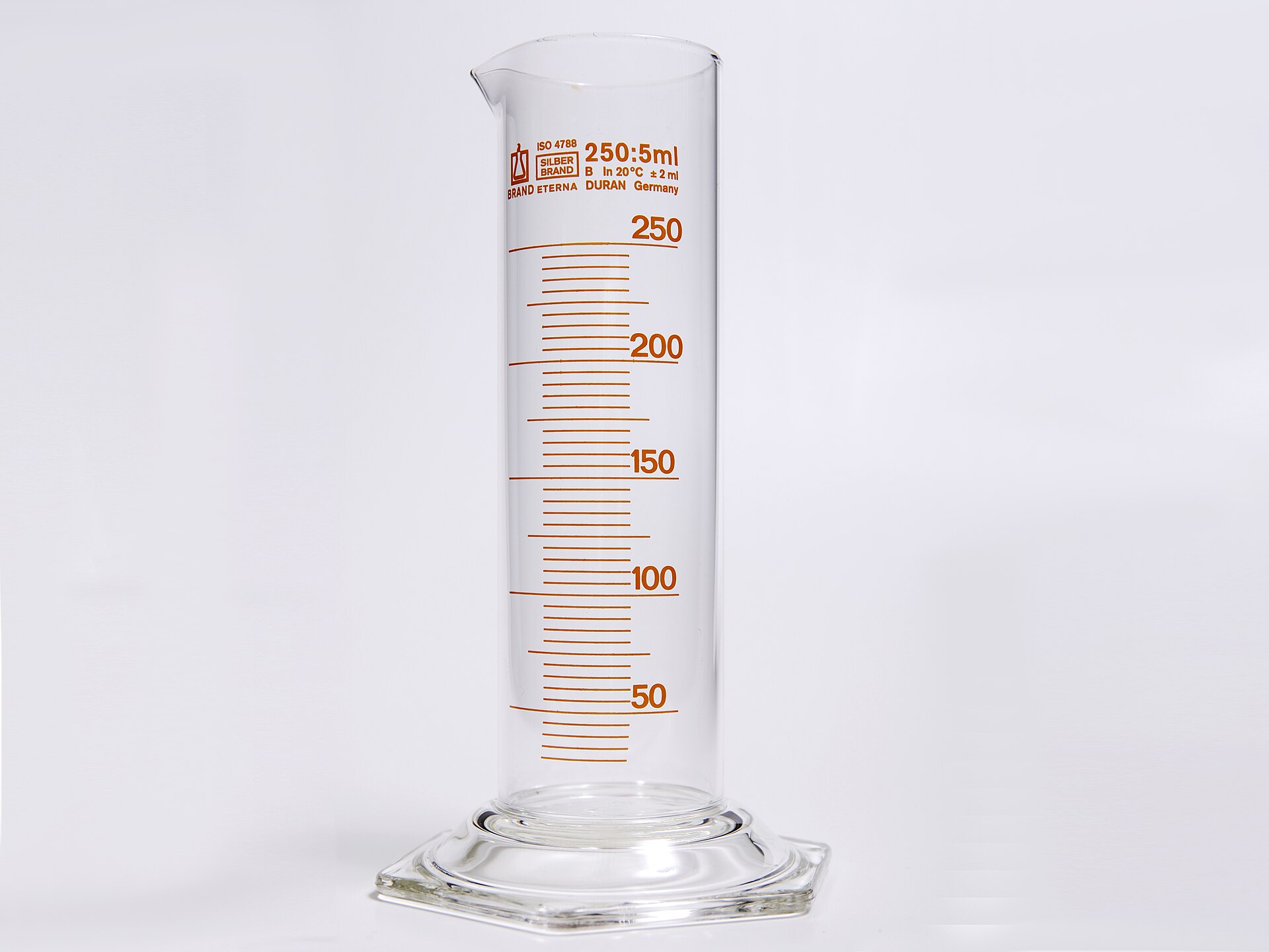
A tall, thin column is usually recommended for readability. The practical trade-off is that a narrow column produces more visible level movement for a given withdrawn volume, while requiring sufficient mounting height. A large-diameter vessel may hold plenty of liquid yet provide little movement at minimum output. Obtain the drawing rather than judging scale readability from an isolated product image.
Where one model cannot cover the full range acceptably, ask whether two documented measuring ranges or another approved method is more practical. Extending every low-dose test indefinitely can make routine checks impractical. The decision should balance readable withdrawal, representative operating conditions and the time operators can consistently devote to the task.
Timing contributes another limitation. If the combined start-and-stop timing bound is assumed to be one second, that alone represents about 3.3% of a 30-second interval or 1.7% of a 60-second interval. These calculated examples isolate timing; they exclude scale error, endpoint reading, changing flow and the operator's actual technique. A longer test reduces that particular relative contribution without proving the entire result accurate.
At very low stroke rates, also record the control mode and the number of delivery events represented by the interval. A short observation that includes only a few strokes may be sensitive to when timing starts. Ask the pump manufacturer for a suitable test duration at that setting. Do not adopt a universal minimum stroke count without a documented basis.
Read the time basis on a direct flow scale
A graduation labelled GPH is useful only with its specified procedure. One supplier describes a one-minute test for its dual scales, while another bulletin gives a direct US-gallons-per-hour reading after 30 seconds. The same elapsed time cannot be assumed merely because both accessories show a GPH scale.
For example, 100 mL withdrawn in 60 seconds represents 6 L/h. The same withdrawal in 30 seconds represents 12 L/h. Reading a direct-flow scale under the wrong timing convention can therefore create a twofold error in this example. When the scale basis is unclear, use a documented volume difference and the measured time, then calculate the flow.
Include the scale photograph and timing instruction in the maintenance record. State whether gallons mean US gallons, and retain the chosen units on the test sheet. Reordering a similar-looking column with a different direct-read interval should trigger a procedure review before operators use the replacement.
Keep the measuring arrangement representative
A drawdown test changes the liquid source from the stock tank to the column. Ask how the proposed installation affects suction level, line resistance and venting. Record the column's starting and ending liquid elevations relative to the pump, together with the normal stock-tank operating levels. A calibration result belongs to the conditions under which it was obtained.
Leave the discharge operating under its intended conditions when the approved procedure requires it. One bulletin establishes system pressure before measurement. Opening the discharge into an atmospheric container instead may answer a different question from the installed test. Likewise, a filled column must have the specified vent path; fitting a cap is not evidence that the assembly should operate as a sealed vessel.
Some engineered calibration stations use a different filling arrangement to preserve actual suction pressure and controlled discharge pressure during calibration. Their instructions illustrate why architecture matters. They do not authorise moving an ordinary plastic drawdown column onto a pressurised discharge line. Obtain the exact layout and pressure limits for the assembly being purchased.
During acceptance, look for repeatable readings and a liquid boundary that can be identified consistently. If the level oscillates or the result changes during the draw, investigate the pump, valve condition and test arrangement before accepting the mean as reliable. Column bounce is identified in manufacturer guidance as a possible indication of dirty or worn pump check valves; it is a diagnostic clue requiring investigation.
Retain individual repeats rather than only their average. For an illustrative sequence of 98, 100 and 102 mL in separate 60-second draws, calculated outputs are 5.88, 6.00 and 6.12 L/h. Their mean is 6.00 L/h, but agreement around that mean does not establish the column's absolute accuracy. The sequence is a calculation example, not a test or a performance claim for any listed accessory.
Put materials and service details on the order
Specify the fertilizer formulation, concentration, operating temperature and cleaning liquids. Request separate identities for the transparent tube, end caps, seals and adapters. Manufacturer documentation distinguishes borosilicate glass from several end-cap and gasket options. A listing labelled PVC or PVDF may not identify every wetted component.
Check pressure and temperature limits against the actual configuration, including filling and abnormal conditions addressed by the approved installation. Do not transfer a different manufacturer's pressure rating to the candidate. Require a defined vent or overflow route, connection standard, support arrangement and cleaning instructions. Female half-inch wording alone does not establish whether the thread is BSP or NPT.
Retain the manufacturer, exact part number, approved drawing and scale specification for repeat orders. Ask whether a replacement tube or seal is available separately and whether replacing it changes the calibration status. An accessory used repeatedly for checking flow needs an identifiable service configuration, even when its initial purchase price is modest.
Before accepting a substitute, compare its scale direction as well as its capacity. A top-zero withdrawal scale and a scale showing remaining contents require different reading conventions. Write down the initial and final values explicitly. A familiar column shape should never replace checking what its markings actually represent.
A compact specification to send with the enquiry
Complete both flow rows before selecting a capacity. Have the supplier return its proposed model against the same inputs, including any conditions that require a different range. Keep the accepted response with the operating procedure so the next technician can reproduce the measurement.
| Field | Specify | Confirm before purchase |
|---|---|---|
| Maximum test duty | Flow and chosen test duration | Required drawdown and usable span |
| Minimum test duty | Flow and acceptable test duration | Readable divisions and stated scale error |
| Installation | Liquid elevations and suction layout | Venting and permitted pressure conditions |
| Repeat order | Fluid and exact assembly | Materials, ports, drawing and service parts |
One Alibaba candidate for a small-volume enquiry
The listing below is a 300 mL UPVC flow calibration column. At the time of checking it showed ten sold and three historical product reviews, with no new rating in the past year. The displayed minimum was five pieces. These are listing observations, not evidence of volumetric accuracy.
The supplier's series table identifies the model as a 300 mL column with 50 mm diameter, 320 mm height and a female half-inch connection. Treat these as seller-stated fields pending an exact drawing. The page also contains generic series material descriptions and a 1.0 MPa pressure field; neither establishes the complete material configuration or an approved working-pressure rating for the proposed installation.
The seller showed nine years on Alibaba and a trading-company classification. This is an enquiry candidate, not a verified factory or an approved calibration instrument. Request the actual manufacturer, usable span, smallest division, volumetric error, materials, thread standard and installation instructions before ordering.
Approve the selection when maximum output fits the documented measuring span and minimum output remains readable within an acceptable test time. Preserve the drawing, scale basis and installed baseline together. That record makes a later replacement or change in dosing duty a checkable decision.
Share this article