6 Checks Before Replacing a Dust Collector Pulse Valve Coil
A silent pulse valve is easy to blame on its coil, but a replacement coil cannot fix a timer output, a loose connector, a stuck pilot or a torn diaphragm. These six checks find which part actually failed.
Disclosure: We may earn a commission if you purchase through links on this page, at no additional cost to you.
A dust collector can have a healthy fan and clean compressed-air header while one row of filters receives no pulse. The silent valve is easy to blame on its solenoid coil. Yet a replacement coil cannot fix a timer output that never energises, a loose connector, a stuck pilot or a torn diaphragm. The useful question is narrower: is the coil the failed part, and what evidence identifies an electrically and mechanically compatible replacement?
This guide follows that decision from the collector to the spare-parts order. It concerns pulse-jet baghouses and cartridge collectors with electrically operated pilot valves. The installed valve and collector manuals take precedence over a generic sequence, especially for hazardous dust, classified locations and any work that exposes stored air or live electrical parts. A qualified person should isolate electrical power, lock out the equipment and bleed the compressed-air system before opening a valve or removing a coil. Live diagnostic measurements belong to a qualified electrician using the site's safe-work procedure.
First establish whether the valve was actually told to fire
On an on-demand cleaning system, a rising differential-pressure reading does not mean every valve should pulse immediately. The controller starts a sequence when its high set point is reached and stops at the low set point. A timer then energises solenoids in order; pilot action permits the diaphragm valve to release a short burst from the manifold. Manufacturer troubleshooting therefore begins at the compressed-air supply, then checks power to the controller and timer, and then watches the timer's output indicators advance.
Record the symptom before disturbing wiring. Is a single station silent during an otherwise regular sequence? Are several stations quiet? Does the entire cleaning system fail to start despite the high set point? Is there continuous air leakage rather than no pulse? These are different failures. If every station is silent, start with the cleaning enable signal, controller, timer and air supply. If only one station fails while neighbouring valves fire, compare that station with a working one. A missing flash at its timer output, a flash without voltage at the field connector, and proper voltage at the coil with no valve response each direct the repair to a different place.
For collectors that clean only on demand, confirm that the system is actually in a cleaning cycle before declaring a particular output dead. Do not defeat interlocks or jumper control terminals as a casual field test. Controller-versus-timer isolation is work for a qualified electrician, not an operator shortcut.
Check 1 — Is compressed air reaching the manifold
Confirm that the supply valve is open and the manifold has air at the pressure specified for that collector and valve. Read pressure while the system is operating; a static gauge reading can hide a supply that sags when adjacent valves pulse. Inspect the regulator, drains and obvious leaks. Moisture, oil and debris can interfere with a pilot or diaphragm. The required pressure and air quality must come from the installed equipment's documentation, not from a number copied off another manufacturer's valve listing.
If the whole bank has weak or absent pulses, the air header is a better first suspect than a batch of simultaneous coil failures. If one valve alone stays silent while the header supports its neighbours, continue downstream. A continuous hiss at that station calls for a separate leak or valve-seat diagnosis; swapping its coil would be an unsupported repair. Equipment troubleshooting material distinguishes a non-energised pulse valve from diaphragm, pneumatic-tubing and valve-wear problems.
Check 2 — Does the controller send a pulse to this station
Observe the timer indicators through a complete cleaning sequence and note the station number. A lit output LED indicates a command at the board; it does not prove the correct voltage reaches the coil under load. An unlit LED at one position may implicate timer configuration, an output fault or a disabled channel. If the board sequences but the field valve does not fire, a qualified electrician can check the output and connector against the collector wiring diagram.
Avoid interpreting a generic LED as a current monitor unless its manual says that is what it measures. Timer documentation warns that low supply voltage may still light an LED while being insufficient to operate valves. It also identifies damaged or disconnected pneumatic tubing and low compressed-air pressure as distinct causes of absent pulses. The correct test points, voltage range and pulse duration depend on the installed timer and valve. Record them from their nameplates and manuals before making a live measurement.
When several outputs misbehave, trace a common supply, neutral or controller signal before buying multiple coils. When only one output is affected, compare the same measurements at a working adjacent station under equivalent conditions. That comparison is often more informative than an arbitrary resistance value found online.
Check 3 — Is the fault in the wiring or connector
After isolation, inspect the cable run from terminal board to solenoid. Look for loose terminals, corroded pins, damaged insulation, a cracked cable gland and evidence that water or dust entered the plug. Verify that the connector seats and its seal is present. A coil may be sound while an open conductor prevents it from receiving a pulse. Conversely, heat damage at the plug may indicate a bad contact that a new coil alone will not correct.
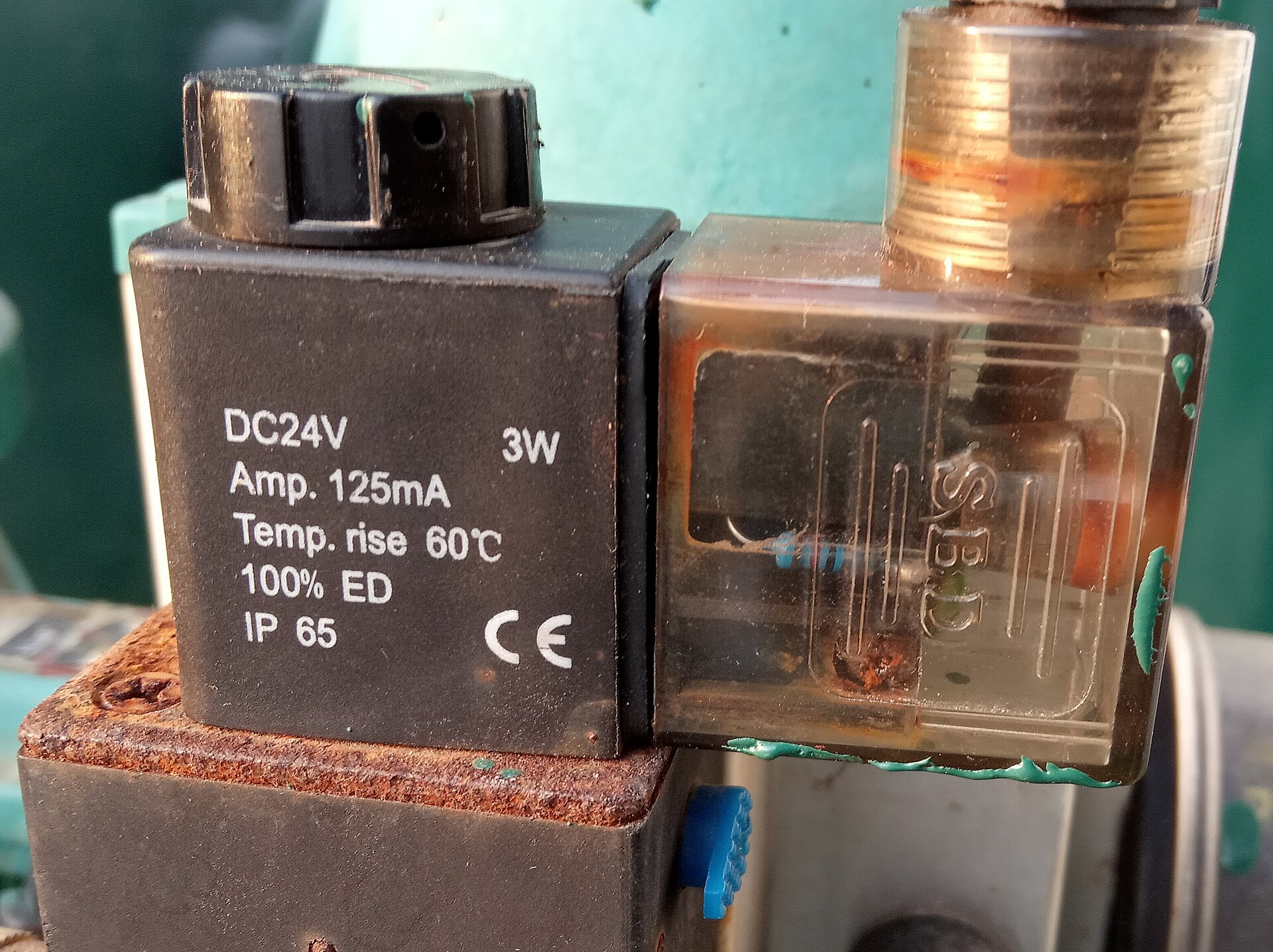
The common visual trap is assuming that any similar black rectangular coil has the same electrical connection. A DIN-style plug's form, pin spacing, gasket, orientation and cable entry all matter. Some assemblies use flying leads instead. Photograph the installed plug and the coil marking before disassembly; capture both the terminal arrangement and the pilot tube. Ask a supplier whether the quoted coil includes the connector. An advertised coil body can arrive without a plug or retaining hardware.
If the station has the correct timed voltage at the connector under the conditions specified by the manufacturer but does not actuate, move to the coil and pilot. If voltage is missing there, repair the control circuit first. Never infer coil failure from a timer LED alone.
Check 4 — What does the coil test actually show
With power isolated and the coil disconnected, an electrician can use the manufacturer's procedure to test continuity or resistance and examine the body for cracks, overheating or moisture ingress. An open winding is strong evidence of coil failure. A short or leakage to the frame also warrants removal from service. A finite ohm reading, however, establishes neither correct magnetic force nor proper operation at temperature; it cannot clear a sticking armature or an inadequate supply voltage.
Do not compare an AC coil's resistance with a DC coil's, or treat a single internet ohm figure as a universal pass limit. Voltage, frequency, winding design and coil family alter the expected result. A known-good matching coil may be useful for controlled diagnosis only if the exact electrical and mechanical specifications are already established and the site's maintenance procedure permits the substitution. Energising a loose coil or running it away from its intended armature can create a hazard; follow the maker's installation instructions.
If the installed part number is legible, preserve it. If it is worn off, record the valve body identification and the pilot assembly code, not just the collector model. The same collector family may have been built with different valve suppliers or modified during maintenance.
Check 5 — Can the pilot and diaphragm move air
The coil creates a magnetic field; the pilot assembly still has to move and release or admit air in the way its valve design requires. A fouled or seized armature may leave a healthy coil unable to trigger the main diaphragm. A damaged diaphragm, blocked bleed path or loose pilot tubing can also prevent an effective pulse. The fact that a coil clicks does not establish that the filter row received a proper blast.
Use the valve manufacturer's service method to separate these possibilities after isolation and depressurisation. Check the pilot tube and moving parts for wear or contamination, the diaphragm for damage and seating, and any remote pilot line for disconnection or kinks. Do not dismantle an unknown valve under pressure. Solenoid-pilot-operated diaphragm valves designed for reverse-jet dust collection explain why an electrical command and an actual air pulse must be checked separately.
If the pilot moves but the main valve leaks or fails to discharge, obtain the appropriate diaphragm or valve service kit rather than another coil.
Check 6 — Does the replacement match the installed assembly
Order from the installed valve's identification, not from a photograph of a similar collector. Request a written cross-reference from the seller if you cannot confirm every field below. The purchase order should identify the chosen variant, because a listing that displays five voltages is not one universal coil.
| Field to confirm | Why it matters |
|---|---|
| Valve and pilot model or original coil code | The electrical part must fit the exact pilot assembly, not merely a valve body size. |
| Rated voltage and AC or DC | A 24 VDC coil is not a substitute for 24 VAC; 110/120 and 220/230 claims require the maker's stated range. |
| AC frequency and power rating | A visually similar winding may draw a different load or behave differently on the timer output. |
| Coil bore, height and retention | The body must sit correctly on the armature tube with its intended nut or clip. |
| Plug or lead configuration and protection | Pins, gasket, cable entry and environmental rating must suit the location. |
| Duty and temperature limits | The electrical and thermal rating must suit the pulse pattern and enclosure conditions. |
A real marketplace example shows why the offer is a lead rather than a certificate. An Alibaba listing from Ningbo Aiwofu Automation Technology offers 400325-117, -107, -205, -201 and -142 variants and states fit for SCG353A043/SCG353A044-type pulse valves, with selectable options at 220 VAC, 110 VAC, 48 VAC, 24 VAC and 24 VDC respectively. The supplier storefront shows eight years on Alibaba and the offer has a one-piece minimum. Emerson separately identifies an ASCO 400325-117 part in its own catalogue. These facts make the offer a sourcing lead, not an OEM authenticity or interchangeability certificate.
The marketplace page also contains mismatched generic attributes, including an unrelated application field. It does not establish the installed valve's exact build, electrical loading, connector geometry or the seller's traceable origin for every variant. Do not treat the seller's "ASCO Valves" type label as evidence that the supplied part is genuine ASCO. Send the photograph of the old coil and pilot, the collector wiring information and the required quantity. Ask for the specific variant's drawing, voltage and frequency, power or current, dimensions, connector and retention details, environmental rating, lead time, and whether it is genuine OEM or a compatible aftermarket part.
A useful spare-parts record for the next shutdown
After a successful repair, record the failed station, actual cause, valve and pilot codes, coil code and electrical variant, connector style, measured control voltage under the permitted test method, and the supplier's confirmed drawing. Keep a photograph of the old and installed parts with the maintenance record. If multiple valves share an assembly, this information supports a small, controlled spare stock. If the collector has two valve families, label their bins separately. A spare that merely fits over the pilot tube but has the wrong voltage or plug is not useful when the next station fails.
The repair is complete when the timer commands the correct station, the valve produces an audible and observable pulse according to the collector procedure, air does not continue leaking, and the cleaning system behaves normally over a sequence. Differential pressure may take time to respond and is influenced by filters and operating load; it is not by itself proof that a new coil fixed the fault. The purchasing decision follows the diagnosis: replace an electrically failed, exactly identified coil; service a stuck pilot or damaged diaphragm when those are the failed parts; repair supply and control faults before ordering valve spares.
Share this article