Does a Fertigation Stock Tank Need a Bottom Drain?
A bottom drain is a cleanout decision, not a decoration. This guide covers when it earns its place, how to choose the low point and valve, and how to test the drain before it enters service.
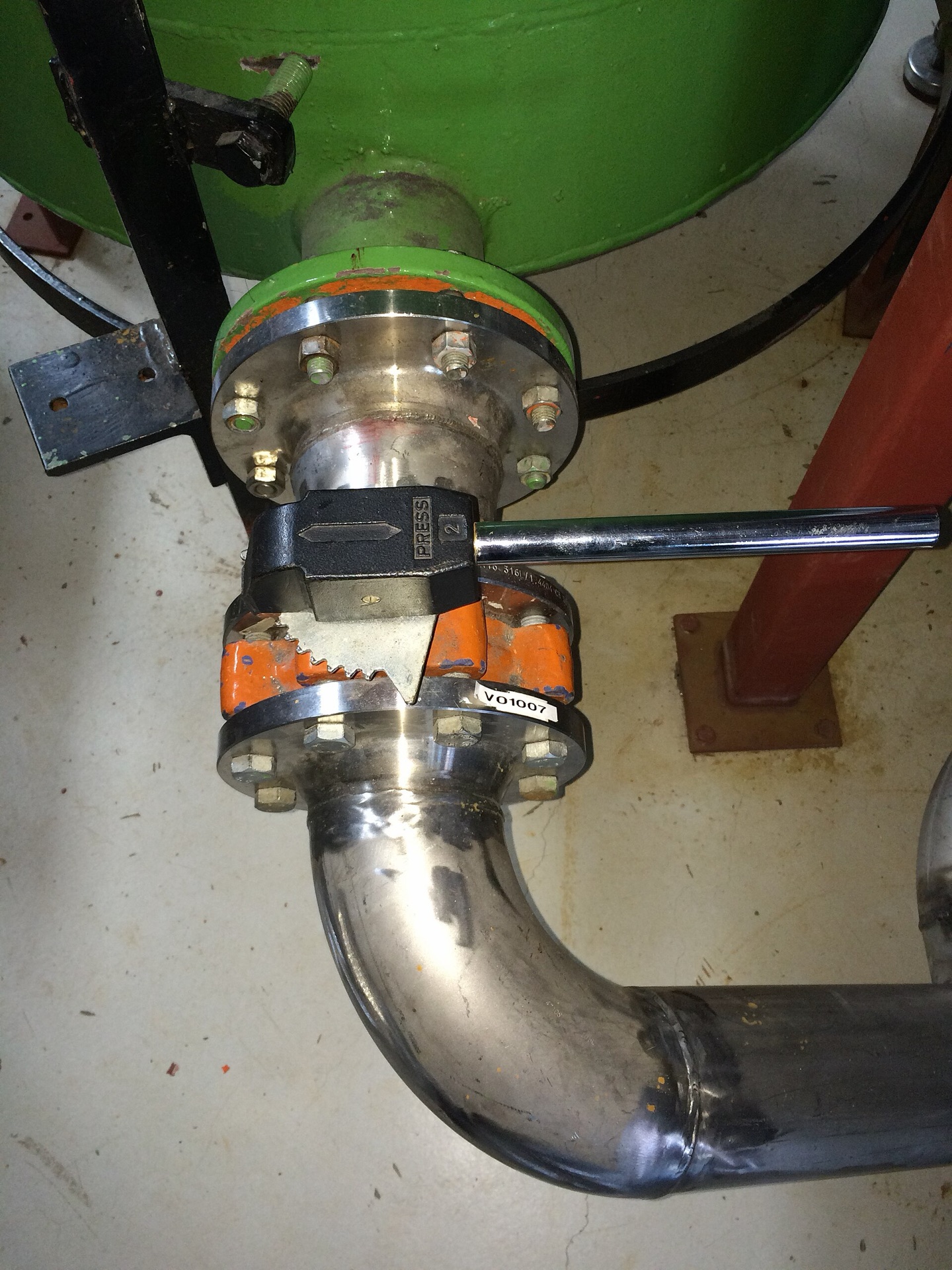
Disclosure: We may earn a commission if you purchase through links on this page, at no additional cost to you.
A practical cleanout, sediment-control and RFQ guide for stock-solution tanks
Not every fertigation tank needs a dedicated bottom drain. A small, openable tank that is emptied and cleaned by hand may work without one. The case changes when the tank is opaque, permanently piped, difficult to enter, exposed to undissolved fertilizer or precipitation, or used for separate concentrates that must be cleaned without disturbing the injection train. In those cases, a low-point drain is a maintenance and contamination-control decision, not a decorative fitting.
Chemigation guidance places a flush valve at the bottom of the stock tank so sediment can be removed after the stock solution is injected, and other extension material treats settled solids and complete drainage as practical cleaning problems. The correct question is therefore not "does every tank need a drain?" but "can this tank remove its settled material safely, completely and repeatably without lifting the tank or sending residue into the suction line?"
When a bottom drain earns its place
| Operating condition | Drain value | What to verify |
|---|---|---|
| Small, open tank; fully soluble product; frequent manual emptying | Usually optional | The operator can reach the low point, remove residue and dispose of the rinse safely |
| Opaque or enclosed tank with no practical internal access | High | The outlet is at the true low point and the valve can be serviced from outside the containment area |
| Suspension, hard-water precipitation or long hold time | High | The drain can pass the expected solids or slurry without becoming the new blockage point |
| A/B or acid/base channels cleaned separately | High | Each tank has an isolated discharge route; rinse water cannot cross-contaminate another channel |
| IBC used only as bulk transfer storage | Depends | The existing bottom outlet may be enough, but check residual heel, valve material and discharge routing |
A drain does not make a tank self-cleaning. A flat bottom can leave a broad residue field around a small outlet; a cone or sloped bottom can direct more material toward the valve; a recirculation return can re-suspend solids without moving them out. Geometry, flow path and cleaning procedure must be considered together.
Separate the four outlets people call a "tank drain"
| Outlet type | Primary job | Common mistake |
|---|---|---|
| Bottom cleanout or flush outlet | Remove settled solids, rinse water and the final heel during maintenance | Treating a small side outlet as if it drains the whole floor |
| Suction pickup | Feed the injector or pump while staying above sediment and submerged at minimum level | Placing the pickup on the bottom so it can "use all the product" |
| Transfer outlet | Move a liquid to another vessel or process line | Assuming its elevation or valve size suits dirty cleanout water |
| Overflow or vent | Admit or release air and protect against overfill | Using it as a substitute for a controlled drain or spill-containment route |
The cleanout outlet and the suction pickup may be close to one another on a small tank, but they should not be specified as the same function. The pickup must protect the injection process during normal operation; the drain must move residue during maintenance. Combining them forces a compromise in elevation, screen protection or valve size.
Choose the low point before choosing the valve
Mark the internal floor shape, the lowest liquid point, the normal sediment zone and the minimum operating level on the tank drawing. On a flat-bottom tank, the lowest point may be a local depression rather than the centre of the floor. On an IBC or molded tank, the manufacturer's outlet may sit above a residual heel. On a cone-bottom tank, the outlet should be aligned with the cone apex and supported so the fitting is not carrying the full tank load.
| Design check | Why it matters | Acceptance evidence |
|---|---|---|
| True low-point location | A valve at the lowest external corner may still leave solids on the opposite side of a flat floor | Dimensioned internal drawing or a filled-and-drained water test |
| Valve bore and line slope | A narrow, level or upward-running line can trap slurry and rinse water | Flow test with clean water and representative residue; no persistent pocket after drain |
| Chemical compatibility | Fertilizer concentrate, acid, biuret or cleaning chemicals can attack plastics, metals or seals | Wetted-material and gasket declaration for the named formulation, concentration and temperature |
| Isolation and containment | A maintenance drain must not become an uncontrolled spill path or a backflow route | Normally-closed valve, cap or secondary isolation, bund or containment, labelled discharge point |
| Service access | The operator needs to see, actuate and replace the valve without entering the tank | Accessible handle, clearance, spare seal or valve plan, and lockout or tagout instruction |
Bottom valve, flush-bottom valve or simple port?
| Option | Good fit | Limit to keep in mind |
|---|---|---|
| Full-port ball valve on a low outlet | Simple flat-bottom or IBC cleanout where the outlet is already engineered and solids are not large | The valve body and downstream elbow can create a pocket; confirm bore and material rather than relying on nominal pipe size |
| Diaphragm or pinch-style valve | Slurry-prone service, or a line where the sealing element should be isolated from the product path | Requires chemical, pressure, temperature and maintenance confirmation; not automatically better for every fertilizer |
| Flush-bottom or tank-bottom valve | A tank designed around a flush seat and low-point discharge where residual hold-up is a major concern | Often a custom or sanitary-industrial component; confirm flange, seat, gasket and tank-wall interface |
| Drain port with removable cap | Small, low-frequency tanks where the operator can control the discharge and clean the port directly | Slow or messy for large tanks; cap removal must be safe at the actual liquid head and chemical hazard |
"Flush" should describe the installed geometry, not just the marketing name. A valve body can be advertised as flush while the tank floor, gasket groove or external elbow still leaves a meaningful dead leg. Ask for a sectional drawing and the residual volume after draining, then test the actual assembly with water before placing a chemical order.
A drain is justified by the cleanout procedure
- Isolate the process. Stop injection, isolate the water and chemical lines, prevent automatic refill and identify any backflow or siphon path before opening the drain.
- Let the stock solution settle as it normally would. The test should represent the real hold time. A tank that drains cleanly immediately after mixing may leave a different heel after an overnight hold.
- Drain to a controlled collection point. Use the approved waste, recovery or dilution route. Do not route fertilizer, acid or contaminated rinse water onto soil, into stormwater or back toward the irrigation source.
- Flush the tank, valve and downstream line. Use the site's written cleaning medium and compatibility limits. Confirm that rinse water reaches the intended collection point and does not bypass the valve.
- Inspect the floor and outlet. Record remaining heel, sediment location, valve condition and gasket leakage. If residue remains away from the outlet, the geometry — not the operator — is the design problem.
- Restore normal operation. Close and cap the drain, reopen only the required isolations, verify the suction pickup is still above sediment and perform a water-only leak and draw test.
Acceptance tests before releasing the tank
| Test | Method | Pass condition |
|---|---|---|
| Low-point drain test | Fill with clean water, drain through the proposed outlet and measure the remaining heel at the marked level | The remaining volume is known, repeatable and acceptable for the formulation and cleaning plan |
| Sediment-path test | Add a safe, visible surrogate approved for the test, then observe where it collects | Material moves toward the outlet, or the drawing identifies the residual zones that must be cleaned manually |
| Valve and seal test | Cycle the valve at empty, normal and maximum head; inspect flange, gasket, cap and downstream joint | No leakage, binding or inaccessible service point |
| Rinse-route test | Run the planned rinse volume through the tank and drain line to the collection point | The full route is open and no backflow, siphon or uncontrolled discharge occurs |
| Process-restoration test | Refill with water and run the injector or transfer pump while the drain is closed | No suction air, drain seepage, unexpected pressure loss or cross-connection is observed |
Repeat these checks after changing fertilizer formulation, tank orientation, valve material, line routing, cleaning chemistry or the normal hold time. A bottom drain is part of the maintenance system, so its acceptance belongs in the same change-control record as the stock solution and injection settings.
What to write into the RFQ
| RFQ line | Supplier must state |
|---|---|
| Tank and floor | Capacity, internal bottom shape, low-point coordinates, access opening, support method and residual heel after draining |
| Drain assembly | Valve type, nominal and effective bore, connection or flange, body and seat materials, gasket, pressure and temperature range, normally-closed arrangement |
| Chemical service | Named fertilizer or acid/base formulation, concentration, pH, temperature, expected solids and the compatibility source — not only "chemical resistant" |
| Discharge route | Line size and slope, maximum run, collection point, secondary isolation, cap or plug, and any anti-siphon or backflow provision |
| Cleaning method | Allowed rinse medium, valve opening sequence, inspection access, spare parts and disposal instructions |
| Evidence package | Sectional drawing, photographs of the installed low point, material declaration, leak test and a water-only drain and flush record |
Sourcing candidates for the drain and tank package
These are sourcing candidates for different buyer roles, not approved recommendations. Listing fields are supplier or platform statements. Exact valve variant, tank outlet position, wetted materials, residual heel, stock and field performance require an RFQ, drawing review and a water or sample test.
Decision rule
Specify a bottom drain when the tank cannot otherwise remove settled material and rinse water safely, or when the cost of manual cleanout, cross-contamination or unplanned downtime is higher than the valve and containment package. Omit it only when the tank's access, geometry and written cleanout method demonstrably achieve the same result. In either case, require a dimensioned low-point drawing, a chemical-compatibility statement, a controlled discharge route and a water-only acceptance test. A marketplace "bottom valve" label is not proof that the installed tank will drain cleanly.
Share this article