Do Drip Irrigation Zones Need Air Relief Valves?
Air relief is a hydraulic-event decision, not a universal drip-irrigation accessory. This guide separates air release, vacuum admission, placement, sizing, and field commissioning before purchase.
Disclosure: We may earn a commission if you purchase through links on this page, at no additional cost to you.
Placement, valve type, and commissioning checks for long runs, slopes, and subsurface drip
The short answer is conditional. An air or air-vacuum relief valve is most defensible when a drip zone has a real hydraulic high point, a long or sloping run, buried laterals, repeated shutdown drainage, or evidence of air locking and back-suction. It is not a universal cure for uneven irrigation. A valve installed at the wrong point, with the wrong function, or without a clean protected outlet can add a leak without solving the original problem.
The decision becomes clearer when three jobs are separated. A valve may release smaller pockets of air while a line is full and pressurised, admit air when a line drains, or do both. Those functions are not interchangeable, and the right choice depends on the hydraulic event and its location rather than the colour or marketing name of a small plastic valve.
What problem are you actually trying to stop
| Observed symptom | More plausible mechanism | First measurement or check |
|---|---|---|
| The zone starts with sputtering, noise, or delayed flow at the far end | Air remains in a high point or long horizontal run during filling | Watch the highest accessible point and compare start-up time across outlets |
| Buried emitters ingest soil or debris after shutdown | Vacuum forms as water drains and outside material is pulled through outlets | Check whether the problem follows a shutdown event and whether the line is subsurface |
| The valve spits water continuously while the zone is running | Wrong valve function, contaminated seat, inadequate seal, or a valve mounted where water collects | Confirm orientation, operating pressure, and intended function |
| Flow remains uneven after an air valve is fitted | Pressure loss, emitter variation, filtration, regulation, or elevation zoning | Measure inlet pressure, downstream pressure, and flow; do not treat the valve as a pressure regulator |
If the symptom is simply low pressure at distant emitters, begin with flow, elevation, filtration, regulation, and pipe sizing. Air relief may improve filling or protect a buried line, but it cannot create pressure that the zone does not have.
Air release and vacuum admission are different functions
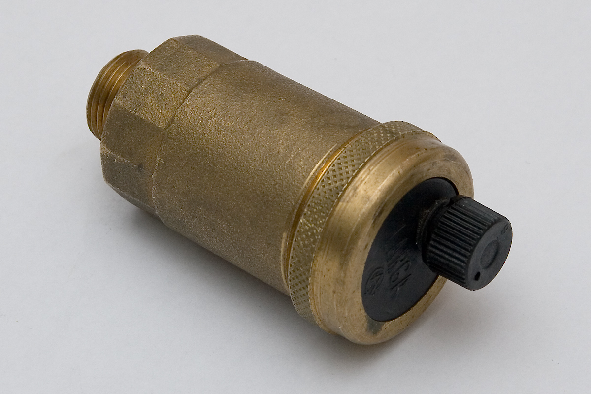
A continuous air-release valve discharges smaller pockets of air that collect while the pipeline is full and operating under pressure. It is useful where dissolved air or trapped bubbles accumulate at a high point. It is not automatically a substitute for a large-orifice air-vacuum valve during filling or shutdown. The required air-flow capacity and sealing pressure must be requested for the exact model.
An air-and-vacuum valve admits a large volume of air as the line drains or pressure falls. That admission function is the part that limits a negative-pressure event in a buried line. Subsurface drip research has linked shutdown vacuum with the risk of drawing soil particles into emitters, so a line that repeatedly drains after shutdown deserves a specific vacuum check rather than a generic accessory.
A combination valve combines continuous air release with air-and-vacuum admission. It can be appropriate on a mainline, submain, or larger zone where both operating air and fill/drain air matter. “Combination” does not tell the buyer the orifice size, pressure range, sealing pressure, or air-flow capacity. Those must be confirmed in a drawing or current datasheet.
Where the valve belongs in a drip layout
The common installation logic is a genuine hydraulic high point, not simply the physical end of a pipe. A local hump in an otherwise level run can be more important than the manifold or end cap. On sloped ground, map both high points where air can collect and low points where water can drain. On subsurface systems, the end of a submain, a flushing manifold, and high points in laterals may need separate evaluation.
The outlet also matters. Keep a relief valve accessible, protected from dirt and flooding, and connected to a clean discharge path. A valve box that fills with soil can turn an air inlet into a contamination path. If the installation is buried, document how the valve will be inspected and cleaned before accepting the layout.
Commission the zone before buying a replacement
1. Map elevation and buried sections
Mark the manifold, high points, low points, end closures, and buried sections. A simple sketch is enough if it shows where water can collect or drain. Note whether the symptom follows one high point, the whole zone, or only a low section.
2. Record clean start-up behaviour
Run the zone with water only. Note the time until the farthest outlets flow steadily, any sputtering, and whether air is expelled at an accessible point. Repeat with the same regulator and valve settings so the comparison remains useful.
3. Measure pressure at two locations
Record pressure near the zone inlet and at the farthest practical point while the zone is running. A pressure drop that remains after air has been expelled points toward sizing, friction, filtration, regulation, or elevation. A single source-pressure reading cannot establish that an air valve is the missing component.
4. Observe shutdown as a separate event
Close the zone normally and watch the high and low points. Note whether water drains, whether the line sucks inward, and whether buried emitters show a later clogging pattern. The shutdown observation is the evidence for an air-vacuum function; start-up sputtering alone is not.
5. Compare with the candidate valve under controlled conditions
If the system design permits a temporary test, compare start-up time, shutdown behaviour, and steady-state pressure with the valve isolated or installed. Improvement in one symptom does not prove that every zone condition is safe. Record the exact model, installation point, orientation, and operating pressure.
Specification to request
| Specification | Why it changes the decision | Evidence status |
|---|---|---|
| Function: continuous, air-vacuum, or combination | Determines whether the valve can handle the event observed | Must be stated for the exact model |
| Nominal connection and thread standard | Prevents a body size from being confused with the pipe connection | Confirm from a drawing |
| Operating and sealing pressure | A valve that does not seal at minimum zone pressure may spit or leak | Request test conditions |
| Air-flow capacity during filling and draining | A larger line may need much more air exchange than a small lateral | Do not infer from port size |
| Orientation and service access | Float mechanisms and seals can fail when mounted incorrectly or buried in debris | Confirm with the current installation drawing |
| Materials and chemical compatibility | Fertigation, chlorine, acid, and saline water can change service life | Supplier documentation required |
Sourcing candidates for technical inquiry
These offers are listed by role, not ranked. Marketplace fields are seller or platform statements, not independent performance tests. Confirm the exact variant, pressure/air-flow evidence, materials, chemical compatibility, and delivered product before treating either listing as suitable for a working zone.
RFQ questions before purchase
- Is this exact listing a continuous air-release valve, an air-vacuum relief valve, or a combination valve? Mark the model code on a current drawing.
- At what minimum pressure does the valve seal, and what were the test medium, temperature, and orientation?
- What air volume can the valve admit during shutdown and discharge during filling? Provide a curve or test table for the exact size.
- What are the actual connection dimensions and thread standard? Is the shown size the port, body, or nominal pipe size?
- Which plastics, elastomers, and springs are used, and are they compatible with the buyer’s fertilizer, chlorine, acid, or saline-water program?
- Can the supplier provide a sample, current datasheet, pressure/air-flow test record, replacement seals, and an installation drawing?
Bottom line
An air relief valve earns its place when the zone has a defined air or vacuum event and the valve function, placement, discharge path, and capacity match that event. Map the elevation profile, measure pressure under load, observe start-up and shutdown separately, then confirm the exact model before ordering. If the far end still runs below the required pressure after air has been managed, the remaining problem is hydraulic design rather than the absence of a small relief valve.
Share this article