How to Choose a DC Extension Cable for a Mini UPS and Router
5.5 mm outside diameter is shared by plugs that do not fit the same jack. Polarity is not universal, and a thin three-metre lead can lose enough volts to reboot a router on battery.
Disclosure: We may earn a commission if you purchase through links on this page, at no additional cost to you.
If a mini DC UPS has to sit near a fibre ONT or router, but its output lead is too short, the tidy fix is often a low-voltage DC extension cable. The hard part is that a cable that physically plugs in can still be the wrong cable. A 5.5 mm outer barrel can have different centre openings; the supply and router can use different polarities; and a longer, thin lead can lower the voltage at the device.
Start with the exact power path: mini UPS output, extension, then router or ONT input. Read the UPS manual and the device label before shopping. The extension should preserve the specified voltage and polarity, match both connector ends, carry the actual load, and remain short and substantial enough that the equipment stays stable on battery. "5521" in a listing title answers only part of that check.
Put the extension on the DC side
This guide concerns a cable between the mini UPS's low-voltage DC output and a router or ONT. It does not mean plugging an AC UPS into a wall extension lead; follow the UPS manual for AC installation and outlet use. A DC extension has no converter inside. It does not change 9 V to 12 V, increase the mini UPS's output-current limit, or make a PoE device compatible with a barrel output.
Sketch the connection before ordering. In a typical pass-through extension, the source's existing male plug goes into the extension's female socket, and the extension's male plug goes into the device's female jack. Check the connector on both ends of the actual UPS cable and the device's original power lead. Listing titles may say "male-to-female" without explaining which end is shown first, so request a photo or a simple end-to-end diagram.
Also decide whether one extension is enough. If the ONT and router have separate power inputs, each device needs its own compatible output path unless the UPS manufacturer supplies and approves a splitter for that purpose. A splitter does not create extra power: the combined draw still has to fit within the mini UPS's total output rating, and both devices must accept the output voltage and polarity.
Read barrel dimensions as a specification, not a complete fit test
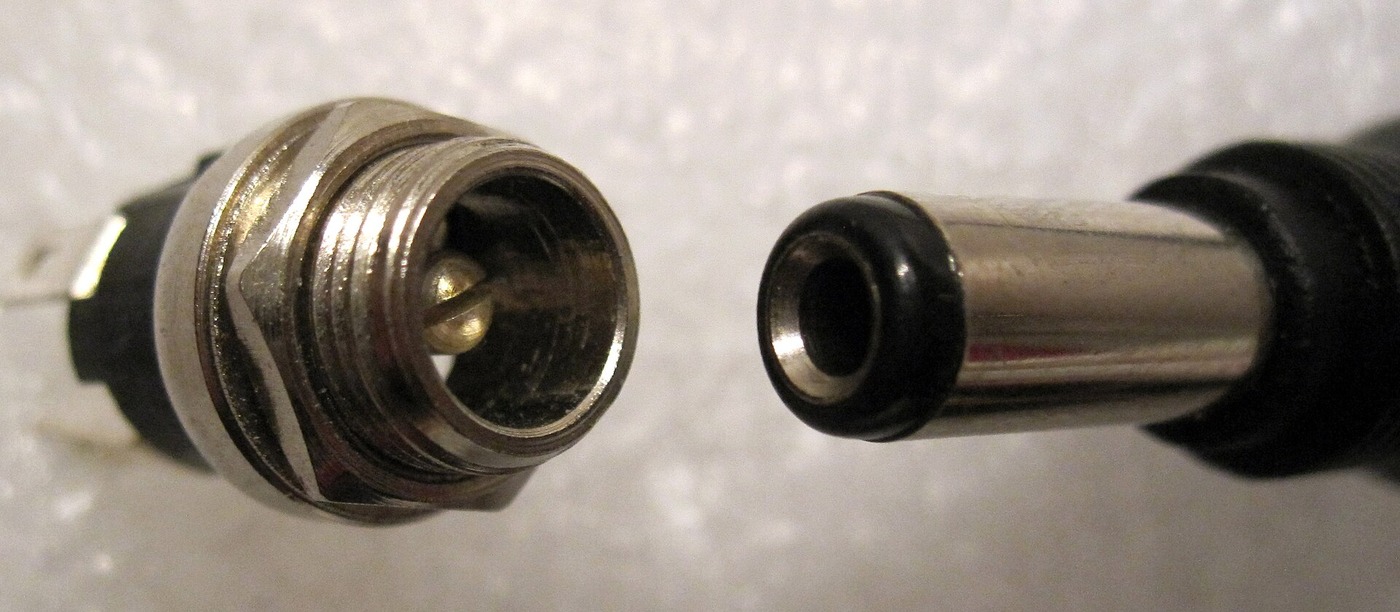
"5.5 × 2.1 mm" normally describes a barrel plug's 5.5 mm outside diameter and 2.1 mm inside opening. A 5.5 × 2.5 mm plug shares the outside diameter but has a wider opening. They are not interchangeable just because they look similar. Manufacturer Bel describes a 2.5 mm plug in a 2.1 mm jack as a potentially loose fit; forcing a smaller-bore plug onto a larger centre pin can damage the jack.
For a cable that extends a 5521 connection, both ends must match the source lead and the device jack, not merely one end. Confirm which end is plug and which is socket, and check any printed dimension against the manufacturer manual. Some mini UPS units include multiple output leads or adapters; Eaton's 3S Mini documentation, for example, lists several output connector sizes, including 5.5 × 2.1 mm and 5.5 × 2.5 mm. That is evidence that connector choice varies by device, not evidence that a given router uses either size.
Barrel length and body shape matter too. A plug may have the right outer and inner diameter but fail to reach the jack's contact, or a long moulded body may hit the router case before seating fully. Same Sky's connector catalogue lists distinct 5.5 mm plug products with different insertion lengths; the exact part drawing, not a generic "5521" label, controls the fit.
Do not treat "it slides in" as a compatibility test. If the plug rocks, drops connection when the cable moves, or needs pressure to stay seated, unplug it and recheck the dimensions. A loose centre contact can create intermittent power loss even when the router's voltage and the UPS's output voltage are nominally the same.
Choose straight or right-angle ends around the device's actual clearance. A right-angle plug can reduce the bend immediately behind a router mounted against a wall, but only if the elbow points away from the case and does not push against a shelf. Check the moulded head dimensions as well as the metal barrel. Avoid stacking a short adapter tip, a gender changer and an extension to make the ends meet; each extra joint is another place for a loose fit or contact resistance. One correctly specified cable is easier to inspect and troubleshoot. Route it where furniture cannot crush it, leave a small service loop, and keep the cable's weight from hanging off the router jack.
Verify polarity and electrical limits separately
The extension should pass the original adapter's polarity straight through. Many barrel-powered networking products use centre-positive wiring, but that convention is not universal. Bel's connector guide specifically advises checking the polarity symbol on the equipment label rather than assuming from plug size. Cisco's 12 V adapter datasheet gives one model-specific example: a centre-positive 5.5 × 2.1 mm plug with a stated barrel length. It does not make centre-positive universal across routers.
An extension cable does not correct a polarity mismatch. If the original adapter and the UPS output differ, use only a manufacturer-approved cable or adapter with a documented wiring diagram. Do not cut, splice, or reverse conductors based on wire colour; colours are not a reliable substitute for the equipment's polarity marking.
Check the voltage before current. The UPS output must match the device's stated input voltage, and it must remain within the range allowed by the device maker. Then check current: the mini UPS must be rated for the router's demand, while the extension and its connectors must be suitable for the current that will pass through them. The lowest-rated component governs the path. A thicker cable cannot raise the UPS's output limit, and a product title that says "12 V" does not tell you the cable's continuous current rating.
Same Sky's product catalogue shows why a connector size alone cannot supply a current rating: different 5.5 mm connector models have different published electrical ratings. For a complete moulded cable, ask for the cable assembly's rating, conductor material and gauge, not just a rating copied from a bare connector or from another SKU.
Choose length by measuring the route and consider voltage drop
Measure the cable route with slack for bends and strain relief. Avoid buying a much longer cable merely because it is inexpensive. The conductor has resistance, and the round trip includes both the positive and return wires. A basic estimate is:
Voltage drop ≈ 2 × current × one-way length × copper resistivity ÷ conductor area
For standard annealed copper at 20 °C, NIST lists volume resistivity as approximately 0.01724 ohm·mm² per metre. This gives an estimate for the wire only; it excludes connector contact resistance, temperature rise, manufacturing variation and the mini UPS's own regulation.
As an illustration, a 3 m one-way extension using true 22 AWG copper (about 0.326 mm² nominal conductor area) has an estimated loop resistance near 0.32 ohm at 20 °C. At 1 A, the wire-only drop is about 0.32 V; at 2 A, about 0.63 V. Those are calculations, not a claim that a particular 22 AWG listing uses copper or is safe at either current. The marketplace candidate below states "5521" and 12 V in its indexed title, but the current cable gauge and continuous load rating have not been confirmed from the live listing.
At 12 V, a few tenths of a volt can matter if the router already receives voltage near the bottom of its permitted range, especially during startup or a battery transfer. There is no single allowable voltage-drop percentage that can be applied to every router: use the router maker's input range and observe voltage at the device end under the real load. Belden's DC reach tool likewise treats source voltage, current, wire gauge and allowed drop as separate inputs rather than inferring reach from nominal cable length.
If the route is long, first consider moving the mini UPS closer to the router or using a shorter, better-documented lead. Do not solve a voltage-drop problem by choosing a larger UPS output voltage. A 12 V router must not receive 15 V simply because the longer cable loses some voltage unless the manufacturer explicitly specifies that operating range.
Test the whole path before depending on it
Test the installed arrangement with the actual UPS, cable, router, ONT and normal network load. Keep the original adapter and cable available so you can compare behaviour. Do not place a meter in current mode directly across a power jack; that can short the output. If measuring voltage, use a suitable inline barrel breakout or a properly rated meter arrangement that cannot bridge the centre contact to the outer sleeve.
- With power disconnected, compare connector dimensions, plug and socket orientation, and the polarity markings for the UPS output and device input.
- Connect the extension without force. Confirm both plugs seat fully and the cable does not pull sideways on either jack.
- Restore power and check that the router starts normally. Watch for repeated booting, a flashing power indicator, unexpected heat, smell, or an unstable plug.
- Check the device-end voltage under its normal workload if you have the correct breakout and meter. Compare it with the device maker's permitted input range; no-load voltage alone does not reveal cable drop under load.
- With the UPS fully charged and following its manual, repeat the check while the mini UPS is on battery. The router and ONT should remain stable through the transition for the exact configuration tested.
If the equipment reboots only when the extension is fitted, remove it and restore the original lead. That points to a cable-path problem, but does not by itself prove whether the cause is connector fit, polarity, voltage drop or a defective cable. Change one item at a time and record the result. If the cable or plug becomes warm, stop using it and ask the supplier for the assembly rating and test data.
What to request from a cable supplier
Before ordering a marketplace cable, ask for a photo of the exact selected variant beside a ruler or calliper, connector gender at each end, inner and outer diameters, barrel insertion length, one-way length, conductor material, wire gauge or cross-section, continuous current rating, voltage rating and polarity continuity. Ask whether the listing is a single cable or a bundle, and whether the displayed Product ID remains the same for the chosen length and connector option.
Do not assume that "5.5 × 2.1," "12 V," a review score or a supplier badge proves the cable's current capacity or router compatibility. A product can be mechanically correct yet under-specified electrically. Buy only after the supplier confirms the exact variant in writing and the resulting path stays within the UPS and router documentation.
Equipvia may earn a commission from qualifying purchases through this link. The link resolved to Product ID 1601122113734 during review. CPS resolution does not verify the seller's technical claims, the cable's gauge or current rating, affiliate eligibility, or commission attribution. Check the actual selected variant and current terms before ordering.
The listing's supplier display fields, such as tenure and rating, are marketplace values, not a verification of the selected SKU, cable gauge, continuous current capacity, copper content, or router fit. Treat the link as a sourcing lead and confirm the exact cable specification with the supplier.
The practical answer
Match both connector ends and polarity, keep the cable no longer than the route requires, and verify voltage and behaviour at the device under load. A neat-looking extension is only suitable after the complete DC path passes those checks.
Share this article